The Grid Dip Oscillator (GDO) is one of the most important instruments for amateur radio constructors. It was primarily used for tuning resonant circuits, but with a bit of ingenuity, it has a wide range of applications. The following text introduces this instrument and some of its potential uses, without aiming to be exhaustive.
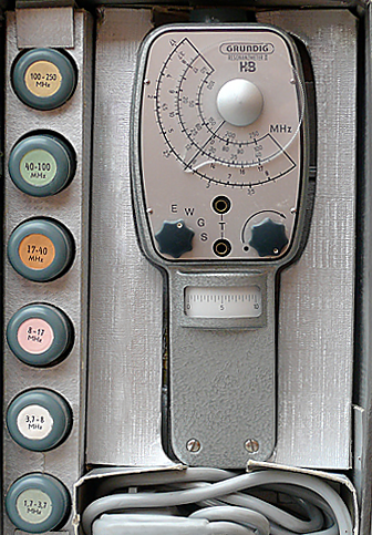
I had long planned to build a GDO, but due to a lack of time, the project was never realized. Then, at the Budapest Amateur Radio Market on November 6, 2016, I stumbled upon a Grundig HZ Type 701 GDO in the hands of HA7HD (www.szepradiok.hu). When new, this was an expensive instrument, launched in 1961 for 155 West German marks, which today would be equivalent to 327 euros, or roughly 100,000 forints. The instrument, which is more or less intact, works flawlessly, and its frequencies are surprisingly accurate even today. For some unknown reason, the power switch (which is integrated with the indicator adjustment potentiometer) had been rewired (its two connections were bridged with solder), so the device couldn’t be turned off and operated continuously when plugged in. I removed the rewiring, and the switch turned out to be flawless.
| Country | Germany |
| Manufacturer | Grundig Radio-Werke G.m.b.H. |
| Year(s) of manufacture | 1960 |
| Form factor | Handheld instrument |
| Frequency range | 1.7 MHz – 250 MHz |
| Vacuum tube(s) | EC92 |
| Power supply | AC 110 V or 220 V / 10 W |
| Operating modes | E: receiver / monitorG: oscillator / dip meterW: absorption wavemeterS: transmitter (50 Hz modulated) |
| Frequency (bands) | 1.7 – 3.7 MHz3.7 – 8 MHz8 – 17 MHz17 – 40 MHz40 – 100 MHz100 – 250 MHz |
| Frequency accuracy | ±1.5 % |
| Audio output | Headphones or external amplifier |
| Enclosure | Metal case |
| Dimensions | 75 × 200 × 55 mm |
| Weight | 0.8 kg |
| Notes | In like-new condition |
| Price | First year of sale (1961): 155 DM; per Hanns Bauer catalog (1966): 270 DM |


Warning: The device does not comply with current touch protection regulations. It is recommended to power it through an isolating transformer or a residual current device (FI relay)!
The original headphones that came with the device are missing. It is important that the headphones used with the instrument have proper insulation, as they are only separated from the anode voltage by the C1 and C2 capacitors, and the device’s power supply does not meet modern touch protection standards on its network side! The metal casing of the device is connected to the secondary side ground, and there is no protective earth!
Modes of Operation
Gitter-Dipper: Oscillator Dip Meter
The device operates as an inductive three-point connected oscillator (series-fed Hartley connection). The resonance frequency is determined by the inductance of the connected coil and the C1 + C7 capacitance:
(The actual operating frequency deviates only slightly from the value calculated using the Thomson formula, see: W. A. Edson: Vacuum-Tube Oscillators. John Wiley & Sons, Inc. New York, Chapman & Hall, Limited, London 1953. p. 168. http://www.tubebooks.org/Books/vto.pdf.)
When the oscillator starts to oscillate, the amplitude of the oscillation increases until the grid current begins. Due to the increase in grid current, the resonant circuit becomes more heavily loaded, eventually stabilizing at a constant amplitude. When the GDO coil is coupled inductively with another resonant circuit, the loading caused by the coupling reduces the amplitude of the oscillations. As a result, the grid current and thus the damping caused by the triode decrease. The decrease in grid current (dip) is indicated by the measuring instrument. The coupled resonant circuit draws the most energy and causes the greatest decrease in grid current when its resonance frequency matches the oscillator’s frequency.
Prüf-Sender: Test Transmitter
The anode voltage is modulated by the 50 Hz alternating voltage taken from the 37 V coil of the network transformer. Otherwise, it operates the same as the G mode.
Absorptions-Wellenmesser: Absorption Wave Meter
The triode’s anode voltage is turned off. The grid-cathode circuit operates as an RF rectifier. The tuning of the resonant circuit to resonance is indicated by the indicator, and the frequency can be read from the tuning capacitor scale.
Empfänger: Receiver
The triode’s anode voltage is turned off. The grid-cathode circuit functions as an AM demodulator. The received signal is output to the headphone jack. The indicator instrument is turned off. The headphone output is only active in this mode.
Measurements
Oscillator Resonant Frequency
The device operates as an absorption wave meter (W mode). A loose inductive coupling is created between the device’s coil and the circuit under test, and the indicator deflection is monitored as the frequency is varied. The resonant frequency of the circuit is determined based on the maximum deflection of the pointer. This frequency is read off the device’s scale.
For measurements, the weakest (loose) coupling that still allows measurement should be used. Tight coupling may cause a so-called frequency shift, which would distort the measurement result. This applies to subsequent measurements as well
Tuning the Resonant Circuit
The device operates as a high-frequency generator (G mode). We set the desired frequency on the scale. A loose inductive coupling is established between the device’s coil and the tuned resonant circuit (input circuit, high- and mid-frequency filters, etc.). By adjusting the tuning capacitor or the core of the coil, we aim to achieve the smallest deflection on the instrument. When this is achieved, the resonant circuit is tuned to the given frequency.

Crystal Frequency
A 2-3 turn coupling coil is soldered to the leads of the crystal. If the crystal cannot be soldered, a socket is used.
The procedure is the same as for measuring the resonant frequency of a resonant circuit: switch the device to G mode and find the resonance. Since the quality factor (Q-factor) of the crystal is very high (on the order of 10^4), we obtain a sharp and distinct resonance. To find it, slowly adjust the tuning capacitor.
Note that some crystals resonate not only at their nominal frequency but also at its harmonics. For such crystals, we will obtain multiple resonance frequencies.
The accuracy of reading the frequency from the instrument’s frequency scale is limited. More accurate results can be obtained (with about 0.2% error) by reading the frequency from a digital frequency meter. To do this, connect a few turns of coupling coil to the frequency meter input, and after tuning the crystal resonance, bring the powered-on GDO close to this coil, then read the frequency from the frequency meter. Make sure not to accidentally adjust the frequency setting during this process! Another viable method is to tune the GDO to the desired frequency using a digital radio receiver and read the value from the radio.
Transmission Check
The device can be used to detect amplitude-modulated carrier wave signals. Set the device to receiver (E) mode and establish loose inductive coupling with the signal source. Then, adjust the device’s input circuit so that the strongest sound is heard in the headphones. If the sound is too strong, adjust the inductive coupling between the circuits (move the device’s coil further away).
Signal Generator
The device can be used as an approximate high-frequency signal generator or test transmitter (S mode). For this purpose, establish loose inductive coupling between the instrument and the circuit under test. Set the desired frequency using the device’s scale. The level of the high-frequency input signal is controlled by moving the device closer to or further from the test equipment. The generator can emit a high-frequency signal modulated at 50 Hz. If an unmodulated signal is needed, the G mode can be used.
If necessary, an antenna can be connected to the instrument: wind 2-3 turns of wire around the coil and attach the end of the wire to the device’s metal case. The other, longer end of the wire should be left 0.3–0.6 meters long (for a more precise solution, use a length of λ/4).
Capacitance of Capacitors
The capacitance of an unknown non-electrolytic capacitor can be determined as follows: You need a known inductance (e.g., 100 µH) coil, which forms a passive high-frequency resonant circuit with the unknown capacitor. Set the instrument to G mode, couple it loosely with the resonant circuit, and tune it until the smallest deflection is achieved on the indicator. Then, read the frequency from the scale. By substituting the frequency into the following formula, the capacitance of the unknown capacitor can be calculated:
or:
Inductance of Coils
The procedure is the same as for measuring the capacitance of a capacitor, with the difference being that, in this case, a capacitor of known capacitance (e.g., 100 pF) is used. The relevant equations are:
or:
Quality Factor and Losses of a Coil
For this measurement, a precision silver mica capacitor must be connected in parallel with the coil under test. The quality factor of this capacitor is high (Q > 1200), so the circuit quality is essentially determined by the coil itself.
Set the instrument to G mode and begin the measurement in the same way as for measuring the resonant frequency of the circuit. However, initially, set the indicator pointer to one division away from resonance. Then, tune to resonance and read the frequency (f0).
The next step is to detune the GDO towards higher frequencies and observe the indicator pointer. Continue tuning until the drop in signal amplitude decreases by approximately 30%. At this point, read the upper cutoff frequency (f2).
In the third step, tune towards lower frequencies. Beyond resonance, find the frequency where the signal drop again decreases by 30%. This will be the lower cutoff frequency (f1). The quality factor can be calculated using the following formula:
The Loss Resistance:
Mutual Inductance and Coupling Factor
To determine the mutual inductance of two coils coupled together (transformer), the coils are connected in series. Connect the standard capacitor in parallel with the two series-connected coils (L1(1)-L2(4)):

Next, swap the leads of one coil and measure the inductance again (L1(1)-L2(3))!

In the first case, the measured inductance is the self-inductance of the coil and the mutual inductance (the latter also includes the coupling between the coils):
When the leads are swapped, the effect of the flux lines that pass through both coils is also reversed:
By subtracting the two equations from each other, the mutual inductance can be calculated:
A két rendszer közötti kölcsönhatás mértékét a csatolási tényező mutatja meg, melynek értéke 0 és 1 között lehet:
Antenna Resonant Frequency
The antenna is also a resonant system, and its resonant frequency can be determined in the same way as already described. A 1–3 turn coupling loop is placed at the antenna feed point, and the GDO is coupled to it. In G mode, we search for the minimum.

A less accurate solution is to directly couple the GDO with the antenna. Inductive coupling should be established at a distance of 1/4 wavelength from the end of the antenna, where the standing wave has a current maximum.
Half-Wavelength and Quarter-Wavelength Feed Lines
In general, we are not concerned with how fast electromagnetic waves propagate along wires or how the wavelength relates to the length of the wire. An exception to this is the feeding of antennas. If the electrical length of the feed line is an integer multiple of half the wavelength, the cable exhibits interesting behavior: a resistance connected at one end will appear at the other end, but only at the frequency corresponding to the wavelength. This phenomenon can be used to “bring down” the antenna’s base impedance to the lower end of the cable, allowing the antenna to be tuned from the radio side.

Half-Wave Feed Line
A half-wave feed line can be created as follows: cut the cable slightly longer than the required length, taking into account the velocity factor. Solder a few turns of a coupling loop at one end of the cable and couple it to the GDO coil. Short-circuit the other end of the cable. Set the GDO to the desired frequency in G mode. Then, step by step, shorten the cable until resonance is found. At this point, the length of the cable will be an integer multiple of half the wavelength.
Quarter-Wave Feed Line
A quarter-wave feed line can be made in the same way, with the difference that the cable’s end is an open circuit instead short-circuit.
Quarter-Wave Cables as Impedance Transformers
Electrically quarter-wave-long cables can be used as impedance transformers. If the antenna’s base impedance is different from the transmitter’s output impedance, the antenna can still be correctly fed using a quarter-wave cable if the cable’s characteristic impedance is the geometric mean of the antenna’s base impedance and the transmitter’s output impedance.
For example, a 120-ohm loop antenna can be correctly fed with 75-ohm cable from a 50-ohm output transmitter if the 75-ohm cable’s electrical length is a quarter-wavelength. The characteristic impedance of the quarter-wave coaxial transformer is:
Feed Line Length and Velocity Factor
On feed lines and coaxial cables, electromagnetic waves travel slower than in free space. Their speed is less than the vacuum speed (299.8·10^6 m/s) by an amount proportional to the dielectric constant of the medium. For example, on a 50-ohm RG58CU coaxial cable, the wave travels only 66 meters, whereas it would travel 100 meters in a vacuum. The velocity factor of the cable is v = 0.66.
With the help of a GDO, we can determine the velocity factor of a wire with a known mechanical length, or the length of a wire with a known velocity factor. Solder a coupling coil to one end of the wire and short-circuit the other end! Then, couple the GDO to the coil and search for resonance! At resonance, the length of the wire will be an integer multiple of half the wavelength. The first found resonance frequency will be f1.
In the second step, slowly increase the frequency until a new resonance frequency is found. This will be f2. The length of the wire is still an integer multiple of the wavelength, but if it was k times the wavelength in the previous case (k = 1, 2, 3…), it will now be (k + 1) times the wavelength. Using this, the physical length of the wire with a known velocity factor is:
where, if the frequency is substituted in MHz into the formula, the result will be in meters. If v≈0.66 (e.g., RG58/174/213/223 coax), then:
… and if v≈0.85v, then 127 is used in the numerator.
The velocity factor of a wire with known length:
where, in the formula, the wire length should be substituted in meters and the frequencies in MHz.
If the opposite end of the wire cannot be shorted but is instead terminated with an open circuit, resonance occurs when the length of the wire is an integer multiple of a quarter wavelength. In this case, instead of 149.9, you should use 74.95 in the above formulas.
Usage Tips
- Always use the loosest coupling that still ensures a distinct change in the value indicated by the instrument (a sudden rise or drop), meaning the device’s coil should be placed as far away as possible from the circuit being tested.
- Start tuning the device from the lowest frequency on the scale. The first sudden drop of the pointer determines the frequency you are looking for.
- The accuracy of frequency measurements is ±10…20%, but it may be even less with too tight coupling.
- When measuring resonant circuits in the coupling, such as bandpass filters, any circuit that is not of interest at the moment should be shorted with a piece of wire.
- Measure and tune the resonant circuits in the configuration in which they will actually be used.
- Transistors in high-frequency stages often dampen resonant circuits, so they should be removed before taking measurements without power supply to prevent potential damage to the transistor.
If you cannot access the circuit directly with the device’s coil, meaning you cannot establish direct coupling between the coil and the circuit, a probe consisting of two coils should be used. Two twisted wires with 2-3 turns are placed at both ends, using PVC insulated wire. One of the coils should be placed on the dipmeter coil (the coils should not be in contact). Another solution is to wind one turn of PVC insulated wire around the device’s coil (without contact) and connect the other end of the wire to the input of the device being tested.
Troubleshooting
- No dip appears: Check the coupling between the circuit under test and the GDO. If there is sufficient coupling, it is likely that the resonance frequency is not within the frequency range being used. In this case, another coil should be connected to the instrument.
- The dip does not decrease when the circuit is removed from the instrument: This error can be caused by several factors. The first possibility is that the cause of the dip lies within the instrument itself. If this is the case, the real dip must be found elsewhere. If the dip is expected to occur in the same range as the false dip, choosing a coil with a different overlapping frequency range may help (though such a coil is not available for this instrument).
Recommended Literature in Hungarian
References
- Using a GDO (QSL.net): http://www.qsl.net/ m3msm/gdo/gdo.htm
- What Can You Do with a Dip Meter? By Mark Bradley, K6TAF. In QST May 2002, p. 65 .(http://g4rvh.files.wordpress.com/2008/08/waht-you-can-do-with-a-dip-meter.pdf)
- Kenwood DM81 Dip Meter User Manual.
- How to Use a Dip Meter, GDO. 2016 electronics-notes.com. https://www.electronics-notes.com/articles/test-methods/grid-gate-dip-oscillator-meter/how-to-use-gdo.php