This article revives a classic from Janusz Wojciechowski’s cult book Building Electronic Toys: a simple Hartley oscillator that does nothing—except beep endlessly. I once drove my father crazy with it and today it’s still a perfect tool for learning electronics. We explain how it works, show how to rebuild it, and explore Wojciechowski’s quirky ideas for turning this “useless” circuit into fun experiments.
In the 1980s, there was a book in the county library titled Janusz Wojciechowski: Building Electronic Toys (Műszaki Könyvkiadó, Budapest, 1980. Edited by Béla Magyari. Paperback, 262 pages). Its original title was Nowoczesne Zabawki elektronika. It was a cult book in communist Poland, the most sought-after DIY electronics book. First published in 1962, its great popularity led to numerous editions. It always sold out immediately, and buying a copy in bookstores was practically impossible. Libraries had it, but usually only in their catalog, because it was always checked out. Getting your hands on it was like winning the lottery. Fortunately, it was less popular in Hungary, so the library had two or three copies, and with a bit of luck—or a reservation—you could borrow one.

This book contains the following circuit, which is beautiful in its own way because it’s essentially good for nothing. According to experts studying the psychology of play, the greatest joy comes from things that are completely useless. If that weren’t true, we wouldn’t give flowers to women…
Circuit Description
The circuit is essentially a grounded-emitter Hartley oscillator. The Hartley oscillator was invented in 1915 by American engineer Ralph Hartley, who worked at the research laboratories of the Western Electric Company. At that time, it operated with a vacuum tube, but it can be built using any amplifying device (a transistor, FET, operational amplifier, etc.). There are numerous variations of this circuit, and its significance in the history of technology and circuit design is enormous. Even the most modern radio transmitters and receivers still use such circuits, operating across a wide range of frequencies—from several tens of kilohertz up to a few hundred megahertz.

To explain how the device works to my completely non-technical readers, I’ll use a mechanical analogy. Imagine a spring toy! Hang it from something, pull the spring down a little, and let it go! The toy will bounce up and down nicely, but after a while—due to energy losses—it will stop. The pace of the bouncing is determined by the toy’s weight and the quality of the spring. Now, take hold of the end of the spring and start giving it gentle tugs! Notice that if you pull it at the same rhythm as its natural bouncing pace, you can compensate for the energy losses, and the bouncing won’t stop.

The same thing happens with electricity in a Hartley oscillator. Instead of a spring and a little toy swinging, we have the electric field stored in capacitor C1 and the magnetic field in the transformer. The resonance frequency is determined by the elements of the tank circuit, namely capacitor C1 and the primary winding of the transformer (according to the Thomson formula:
f = 1/[2π√(L·C1)]
where the total inductance of the two coils is L=L1+L2). The signal from the tank circuit reaches the transistor’s base through capacitor C2.
If left alone, the tank circuit would eventually stop oscillating, just like the spring toy. But it’s not left alone—there is an amplifying element here: transistor T1. The signal from the tank circuit is fed back to the transistor’s base (point 3) via capacitor C2, and the transistor amplifies it. The amplified current flows through the transistor’s collector (point 5), and this is what “gives the tank circuit a tug.”
(Note: The phase shift of the tank circuit at resonance is 180°, and the common-emitter amplifier adds another 180°, making a total phase shift of 360°. This means the amplified signal is in phase, the oscillator meets the Barkhausen criteria, and oscillation starts.)
One thing to know about a Hartley oscillator is that in practice the resonance frequency is influenced not only by C1 and the coil but also significantly by the characteristics of the driving amplifier (in this case, transistor T1) and the parasitic capacitance of the load. The P 100 kΩ potentiometer sets the transistor’s quiescent base current. If it’s too small (or if there’s an open circuit between points 1 and 2), the transistor won’t operate, the oscillator won’t oscillate, and the speaker will stay silent. A small but sufficient base current is needed for oscillation. However, depending on the potentiometer setting, the resonance frequency also changes—meaning the pitch of the tone heard from the speaker varies. Normally, a Hartley oscillator isn’t tuned this way; this is a deliberately “messed-up” design.

Possible Applications
As I mentioned, the device is essentially useless—except for learning—but Wojciechowski offers plenty of ideas for what it could be used for:
Moisture Detector
For detecting the presence of rain, moisture, water, or rising water levels (e.g., water in the basement, bathtub overflow, etc.—even a child falling into a pool, as the waves reach the sensor). Instead of the sensor shown in Figure 2(b) (brass plates mounted on an insulated, waterproof board tilted by 15–25°), you can simply use two bare copper wires pushed into a sponge placed in a window. When the sponge soaks up water, the alarm sounds. This device can warn you about rain that might endanger clothes drying outdoors, babies left outside, or remind you to close the windows before a storm.
Banjo Instrument
See Figure 2(a). After shorting terminals 1 and 2 with a piece of wire, the pitch can be continuously varied using the P potentiometer. However, if one person quickly turns the knob of the P potentiometer while another person pulls one end of the shorting wire off the 1–2 terminals at the right moment, you get the characteristic vibrato sound. Of course, you can use this circuit as a special musical instrument in an amateur jazz band. In this case, mount the P potentiometer’s knob and the K push button (which replaces the shorting wire for terminals 1 and 2) on a housing shaped like a musical instrument.
Light Sensor for Approximate Illumination Measurement
See Figure 2(c). The pitch of the sound depends on the intensity of light falling on a photosensitive element such as a photodiode, photoresistor, or photocell. This way, you can identify poorly or well-lit areas at work or at home. By illuminating the sensor with different light sources, you can create unique sound effects.
If the sensor is in darkness, the loudspeaker emits a tone around 150 Hz. If the sensor is directly illuminated by a 150 W bulb, the frequency rises to about 2000 Hz. Increasing the capacitance of capacitor C lowers the base frequency; reducing the capacitance of C1 lowers the volume. (Fluorescent lights are not suitable for these experiments.)
Additionally, the device can detect the presence and intensity of infrared radiation—the stronger the radiation, the higher the pitch. You can place the photosensor in the casing of a plastic ballpoint pen fitted with a red filter and connect it to the buzzer with a microphone cable.
Another use of this setup:
- Dawn Alarm: Adjust the P potentiometer so the device is silent in darkness. When enough light hits the sensor, the loudspeaker starts to beep.
- The same idea can be used as a refrigerator alarm: place the sensor inside the fridge (where it’s dark with the door closed), and it will beep when the door is opened.
Testing Device for Electrical Circuits, Diodes, and Transistors
See Figure 2(d). By touching the leads connected to terminals 1 and 2 to various circuits and coils, you can check for continuity. If the tested circuit is intact, you’ll hear a tone in the speaker. (Important: disconnect the circuit from its power supply before testing!)
If you place a diode between terminals 1 and 2 (and reverse its polarity), the tone should only appear in one direction if the diode is good. If there’s no sound—or if the sound appears in both directions—the diode is faulty.
The device can also test transistors:
- For a p-type transistor, insert it in place of transistor T1 (at terminals 3, 4, and 5). After shorting 1 and 2, a tone should sound.
- For an n-type transistor, swap the battery polarity.
Tone Generator for Learning Morse Code
See Figure 2(e). Use the P potentiometer to set the tone to a pleasant pitch, and practice Morse code with a push-button connected to terminals 1 and 2.
Electronic Organ
See Figure 2(f). Connect a few push-buttons (keys), each fitted with a potentiometer for tuning specific notes (e.g., C, D, E…), between terminals 2 and 7. Pressing the buttons will short-circuit them and produce melodies.
The P potentiometer can retune the entire organ after shorting terminals 1 and 2.
Metronome
See Figure 2(a). Place a 33 kΩ/0.5 W resistor between terminals 1 and 2, and a 100 µF/12 V electrolytic capacitor (negative to terminal 6) between terminals 3 and 6. The beat frequency is adjusted with the P potentiometer. For a wider adjustment range, use a different resistor between terminals 1 and 2—the higher its value, the slower the beat.
Alarm Device
See Figure 2(g). Short terminals 1 and 2, and close switch K. Connect a loop of thin copper wire (0.1–0.25 mm) to terminals 3 and 5 through a 50 nF/100 V capacitor. The loop can be as long as you like—even several hundred meters in practice. If the loop is broken anywhere, the speaker sounds an alarm.
“Squeaker” Effect
Connect an LED that changes its brightness by itself (blinking, flickering yellow from an electronic candle, or color-changing) between terminals 1 and 2. Depending on the LED type, you’ll get various sound effects.
“Canary-Tone” Doorbell
Connect a 330 µF/10 V capacitor between terminals 2 (negative) and 4. Between terminals 3 and 4, connect a 2.2 kΩ resistor in series with another 330 µF/10 V capacitor (negative to terminal 3). In this case, the doorbell button acts as switch S1. (Admittedly, it sounds only vaguely like a canary, but it chirps nicely!)
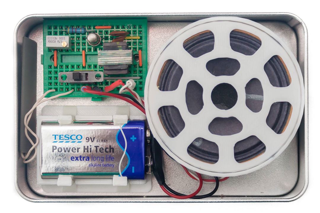
Construction
The circuit can easily be assembled on a small breadboard by any 10–12-year-old. I was about that age when I built mine—on a proper printed circuit board, no less (though that one is long lost; what you see here is a reconstruction on a breadboard). My father would probably lose his mind over it even now—back then, I drove him crazy with it. I used to hide it around the apartment and make it start beeping at the most unexpected times.
When the pitch is really high, it’s surprisingly hard to tell where the sound is coming from, making it difficult to find. But trust me, after a while the beeping really can become maddening…


The loudspeaker is a standard dynamic type commonly found in pocket radios: 8 Ω, 0.25 W. The transformer has a turns ratio of (500…1000):8, with the primary winding tapped at the center. In my opinion, the best option is an output transformer from a Szokol radio, but an output transformer salvaged from an old Japanese pocket radio will also work fine.
As for the transistor, an old germanium type works best. From experience, the circuit doesn’t perform well with every transistor type. It also works with silicon transistors, but it becomes a bit less sensitive. Among germanium transistors:
- AC107 (PNP, hFE = 77, Vf = 230 mV) works well.
- AC125 (PNP, hFE = 84, Vf = 127 mV) and AC128 (PNP, hFE = 58, Vf = 104 mV) make the circuit overly sensitive—it starts squealing even when there is nothing connected between points 1 and 2.


The Sound of Food: Turning Snacks into a Musical Instrument
Here’s a creative twist on our little oscillator project: turn it into an experimental sound generator using food! Connect two probe electrodes to points 1 and 2 of the circuit, and instead of shorting them with a wire. Touch them to various foods—cheese, a raw carrot, an apple, or anything you like. Each type of food has its own electrical properties, and the oscillator responds in fascinating ways.
Now comes the fun part: gently move the electrodes across the surface of the food. The slight variations in contact resistance and moisture content produce quirky changes in pitch and timbre, resulting in strange, unexpected sound effects. It’s almost like turning your lunch into a primitive synthesizer! Interestingly, the sound of some hard cheeses sometimes resembles the mooing of a cow. Some combinations squeal, others buzz, and a few produce warbling tones that sound straight out of a sci-fi movie.
Conclusion
What started as a “useless” little oscillator turns out to be a doorway to endless creativity. From learning basic electronics to building quirky alarms, improvised instruments, and even making food sing, this simple circuit captures the joy of experimentation. Sometimes, the most valuable projects aren’t the most practical—they’re the ones that spark curiosity, laughter, and a bit of whistling madness.