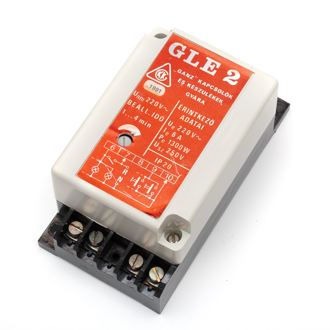
This stairwell lighting timer switch was rescued for me from a building by a friendly electrician acquaintance of mine, Sándor Auffenberg. It had been removed because it was “misbehaving,” but it later turned out to be perfectly fine. According to its label, it was manufactured in 1991—so it’s 30 years old…
I’ve written before about old and modern stairwell timer switches. I mentioned that after the political transition, the Hungarian market was flooded with primitive DIN-rail mechanical timers from the West (and the East), even though Hungarian industry had already been producing high-quality electronic switches. The reason is simple: Western manufacturers had been making such switches since the first half of the 20th century—of course, back then they were purely mechanical, alarm-clock-like devices. And the design hardly changed over the decades, because of that conservative mindset: “If it works, it’s fine as it is”—even when it isn’t. The only real change was outsourcing production to the Far East, turning what was once a neat little device with brass gears and a bakelite housing into a flimsy plastic gadget that wore itself out after a year or two.
Hungarian industry avoided that fate because local engineers only started designing these switches in the 1970s—by which time it was obvious to go electronic. This GLE-2 is already a more mature model, and it’s built almost entirely from Western components.
Inside the Timer Switch
On the front, there’s a knob for the potentiometer, which lets you set the delay between 1 and 4 minutes. The faceplate is covered with a red-marked self-adhesive aluminum foil, and there’s a hole for the knob. That hole was cut after the foil was applied, so it would line up perfectly. And, of course, the tiny half-centimeter cutout fell inside the box. It probably clung to the wall for a while, then dropped and caused a short circuit. That was the fault—thirty years later. Careful design undone by sloppy execution! It wasn’t the designer’s fault, nor the assembler’s, nor the tester’s—it was the helper who stuck on the foil…


I even found its circuit diagram online, and it’s worth a look—a clever design!

Instead of using a monostable multivibrator for the long-duration timing (as in older models), the designer opted for an HCF4541BE programmable timer IC. This type is still in production today, mostly sold under the name CD4541. The only difference is that “CD” is made by Texas Instruments, while “HCF” is from the Swiss STMicroelectronics. Depending on the RC network connected to pins 1 and 2 (220 nF + 12 kΩ + 0…100 kΩ), the internal oscillator runs at 17.6…165 Hz. The logic levels applied to pins 12 and 13 determine the division ratio. Here, both are at logic 0 (L), so the division ratio is 8192. All other control pins (5, 6, 9, 10) are tied to 0, so when powered on, the IC starts counting and counts 4096 clock pulses. During this time, its output (pin 8) is at logic 1 (H), which opens the transistor (marked BC107 on the diagram, but actually a BC182 in reality). This energizes the relay, and the lamps light up.
The counting cycle would repeat after 8192 pulses, but halfway through—after 4096 pulses, i.e., 25…232 seconds (0.5…3.9 minutes)—the output goes low (0), the transistor turns off, and the relay drops out. Since the IC’s output includes a flip-flop, which could be toggled via pin 10 or fully reset, the output stays off from then on until someone presses one of the stairwell pushbuttons. These pushbuttons work by briefly shorting terminals 9 and 10 of the unit, momentarily interrupting power to the IC. The internal reset circuit then reinitializes the IC and restarts the count. This design allows the timer to be restarted mid-cycle, so the delay always counts from the last button press.
A Hidden Feature: Extended Timing
If pins 12 and 13 were disconnected from pin 7 (by cutting a trace on the PCB, for example) and tied to pin 14 (logic 1, H), the programmed division ratio would become 65,536—resulting in a timer adjustable between 3.3 and 31 minutes. Such a timer is quite versatile and can be used in many practical scenarios where a medium-duration delay is needed. Here are some ideas:
✅ Lighting Control
- Stairwell or corridor lights in larger buildings where 1–4 minutes isn’t enough (e.g., hospitals, warehouses).
- Outdoor floodlights that should stay on longer for safety or security after being triggered.
✅ Appliance Delay
- Bathroom fans or heaters that should run after the light is turned off to remove moisture.
- Coffee machines or small appliances that need to power down automatically after a safe time.
✅ Process Control
- Industrial or DIY chemical baths (etching, plating) where timing matters but doesn’t need to be to-the-second precise.
- Glue curing or epoxy setting where a countdown helps maintain workflow.
✅ Safety Applications
- Power-off delay for machines, allowing time to clear the area before full shutdown.
- Locking mechanisms that should release after a fixed time (e.g., timed access doors).
✅ HVAC / Energy Efficiency
- Ventilation systems in meeting rooms or restrooms, running a bit longer after occupancy.
- Heating elements in greenhouses, aquariums, or terrariums for controlled intervals.
✅ Home & DIY Automation
- Soldering iron power-off after a preset time (to avoid burning tips or fire hazards).
- Aquarium lighting cycles or feeding systems on timed control.
Smart Safety Choices
The stairwell pushbuttons connect to the phase through a 270 kΩ/470 nF network, so under normal conditions, they carry about 37 Vpp AC. Of course, that’s only true if phase (L) and neutral (N) aren’t swapped during installation. Even if wired correctly, the switches can still see 230 V if the neutral breaks. The combined impedance of that RC network and the series 180 Ω resistor is 6.95 kΩ at 50 Hz. Adding the human body’s resistance—at worst around 1 kΩ even after the skin is penetrated—the maximum current would still be under 30 mA. That much can be fatal, but is usually survivable—and that’s the worst case. Under more typical conditions (e.g., intact skin), the current would be 0.5…3 mA: unpleasant, but not deadly. Considering that stairwell wiring and switches were designed to meet indoor 220 V electrical safety standards (IP20), this isn’t a big deal in theory—but given that old houses have wires running everywhere, sometimes exposed to leaks, this was a smart choice by the designer.
Summary
The GANZ GLE-2 stairwell lighting timer, designed by Hungarian engineers in the early 1990s, represents a level of ingenuity and durability that puts many modern systems to shame. Instead of the crude mechanical timers that flooded the market after the regime change, this device featured a clever, fully electronic design using a programmable timer IC—flexible, restartable, and safe. Even thirty years later, it remains remarkably reliable, and if it does fail, it’s easy to repair thanks to its simple yet robust construction. Throwing these units away and replacing them with flimsy, short-lived devices is a big mistake—these timers were built to last, and with minimal effort, they still can. In short, what Ganz delivered arguably better than much of what you’ll find on the shelves today.
Én csak azt hiányolom ezekből a lépcsőház-világítási automatikákból, hogy a külső fényre miért nem építettek bele “okosságot”!
Értem azalatt azt
– bármely gomb megnyomására akármely időszakban beindul, majd letölti előre beállított üzemidejét. Holott (benne van a pakliban)
– bármely lépcsőházi gombot akár fényes nappal is megnyomhatják, ámde akkor rögtön felmerül a kérdés – minek égnie nappal a lépcsőházi világításnak?
Én csináltam a GLE-2-be egy fotoellenállás vezérlésű komparátort, amellyel aztán évekig jól működött. Csupán 3 tranzisztor kellett hozzá, s a működés-funkciója kijelzésére kapott egy LED-es visszajelzőt.
Az egészet a már meglévő Ganz GLE-2 típusú (1988-ban gyártott) időzítőbe adoptáltam. (egy az egyben a relét vezérlő BC107A tranzisztor helyére.
Kedves László, ez jó ötlet. Valóban, minek égjen nappal a villany!? A tervezőnek mégis nézzük el, hogy nem épített bele fényérzékelőt, hiszen ezeket a lépcsőházautomatákat többnyire zárt kapcsolószekrényekbe telepítették, ahol mindig sötét van. Megaztán akkoriban az emberek nem voltak annyira hülyék, hogy nappal felkapcsolják a villanyt. Viszont az áramkörébe be lehetett volna iktatni egy közönséges alkonykapcsolót. Ha már Ganz, akkor a GFK3-ast, ami a maga nemében szintén egy ikonikus darab.
Én 2002-ben mégis csináltam meg külső fényérzékelősre!
Lett neki 2 plusz csatlakozó a dobozon (amiket a felső oldalára tettem, az szinte végig üres), s onnan lehetett elvezetni árnyékolt huzallal a fotoellenállásig olyan helyre, ahol már látja a külső – valós fényt. Nálunk például a kapu felett/mellett volt – kisméretű lencsés dobozkában. Ott rendszeresen látta, ha épp nappal volt.
És akkor rögtön letiltotta a GLE-2 elektronika bekapcsolási képességét.
Hétszintes társasházban sokszor beragat a relé 14 db 60 W os izzó miatt,ezért a lépcsőházi automatát úgy kötöttem át hogy az két relét húzzon meg és azokon voltak az izzók!
És hogy nappal ne lehessen felkapcsolni,mert ilyen is volt,a lépcsőházi autómata müködését egy alkonykapcsoló engedélyezte!
Ez sz összes problémát megoldotta!
Minek még külön alkonykapocsoló, ha a belső elektronika meg tudja oldani?
Mellesleg – nálunk a házban legalább 60 égőt (valójában én sohasem számoltam meg) vezérel az automata, de eddig bírta jól, holott szintén 40 éves lehet.