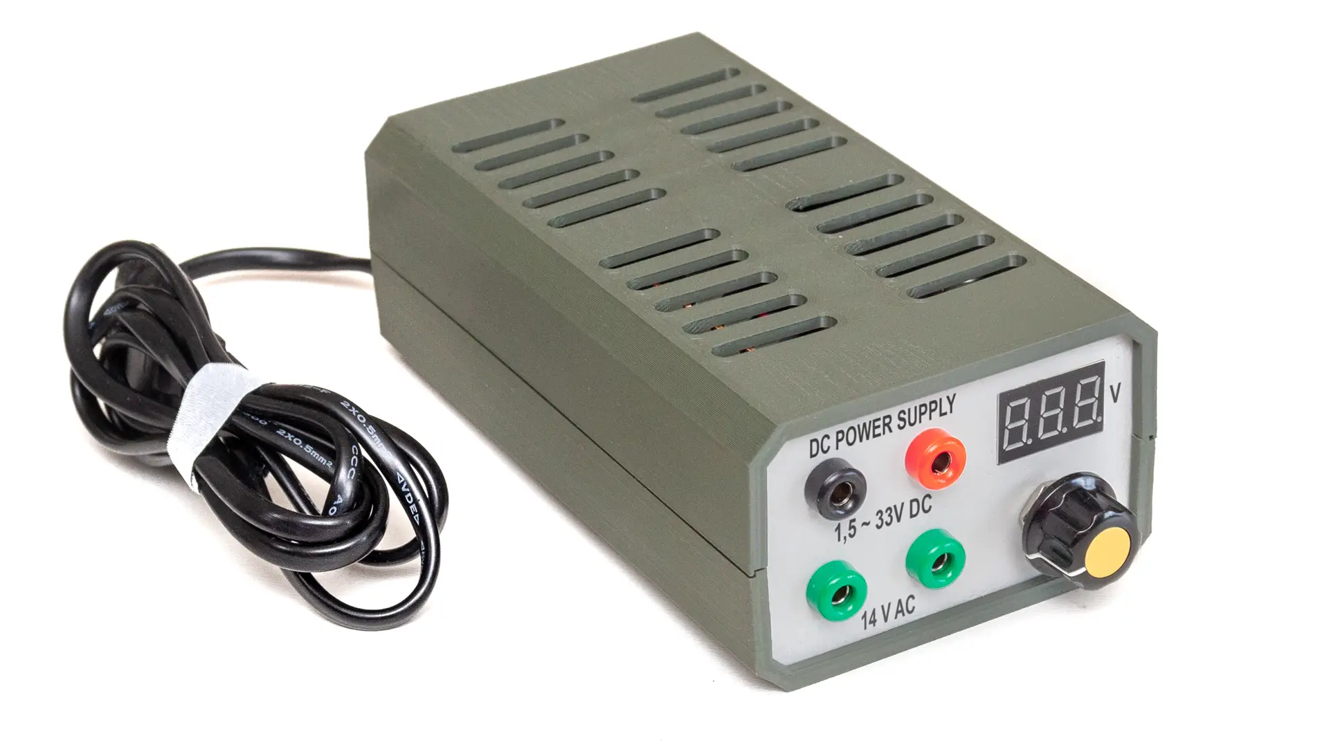
I needed a compact power supply capable of providing roughly 5–20 V DC and 12–16 V AC. Because an AC output was required, I chose a conventional transformer—similar to those used in alarm control units and intercom systems. This project was inspired by the Chordless Lab Power Supply on Thingiverse.
DC Section
The DC side is quite simple: a bridge rectifier and a smoothing capacitor sit on a prototype board, along with a PTC (resettable fuse) protecting the transformer. The AC output is also routed through the PTC. When excessive current flows, the PTC heats up, increasing its resistance, which limits current. Once power is removed and it cools, the PTC resets. This cooling usually takes a few minutes.
Since downstream components can tolerate up to 3 A, the 1.1 A PTC protects the entire device—not only the transformer. The combined current drawn by the AC and DC outputs must not exceed 1.1 A.
This DC section uses an XL6009 DC–DC step-up/down converter module. It accepts 5–32 V input, has four built-in MOSFETs offering up to 94 % efficiency, and a switching frequency of 400 kHz. The output is adjustable from 1.25–35 V. If you don’t need AC, you could instead use an external 230 → 12 V adapter or an internal switching module to build a smaller, lighter unit.
I replaced the onboard trimmer with a 10 kΩ precision potentiometer for fine voltage adjustment. Cheap potentiometers tend to be noisy, causing voltage fluctuations. To stabilize the control signal, I added a 100 nF capacitor between the wiper and ground.

Display Unit
I used a three-wire LED voltmeter to display the output voltage. Its power comes from the XL6009 input terminal, while the measurement input connects to the XL6009 OUT+ terminal. The display is powered at about 22 V, which is enough to keep it lit, while it measures the full 0–35 V output.
If using a two-wire voltmeter, connect it between OUT+ and OUT–. However, below ~3 V, the display may dim and stop reading correctly.
Bill of Materials
| Qty | Component | Specification |
|---|---|---|
| 1 | Transformer | 230 → 16 V, 20 VA |
| 1 | PTC resettable fuse | 1.1 A |
| 1 | Bridge rectifier | 4 A |
| 1 | Electrolytic capacitor | 4700 µF, 35 V |
| 1 | DC–DC converter | XL6009 adjustable module |
| 1 | Precision potentiometer | 10 turn, 10 kΩ |
| 1 | Three-wire voltmeter | 0–32 V, 3‑digit LED |
| 4 | Banana jacks | – |
I also used wiring, M3/M4 bolts and nuts, self-tapping screws, and two M3 threaded inserts to fasten the enclosure.
3D‑Printed Enclosure
Download the STL files from Thingiverse. Print the top/bottom shells and front/back panels. Insert the threaded nuts (heated to filament temperature) into the prints, then let them cool for a secure fit.
After printing the panels, you can label them using a permanent marker, transfer foil, or a laser printer and transfer solution.

Assembly
Follow the schematic diagram. Attach a small heatsink to the XL6009 IC to dissipate heat. Mount everything in the printed enclosure: place the rectifier board in the bottom shell and secure the capacitor (hot glue works well). Screw the XL6009 module over the capacitor. Insert the front/back panels and join the top and bottom shells—adding screw caps if you like. The unit requires no setup and is ready to use immediately after power‑on.


