I inherited this device from my father—he brought it from the Soviet Union at some point. It was manufactured in 1974 and is a typical example of the simple yet extremely robust Soviet devices. It doesn’t contain any “smart” electronic circuits, so there’s nothing in it that could burn out or break. It’s simply built to last. At most, if not properly cared for, rust might get to it—but you can still find quite battered, dusty, and muddy units online that work to this day.
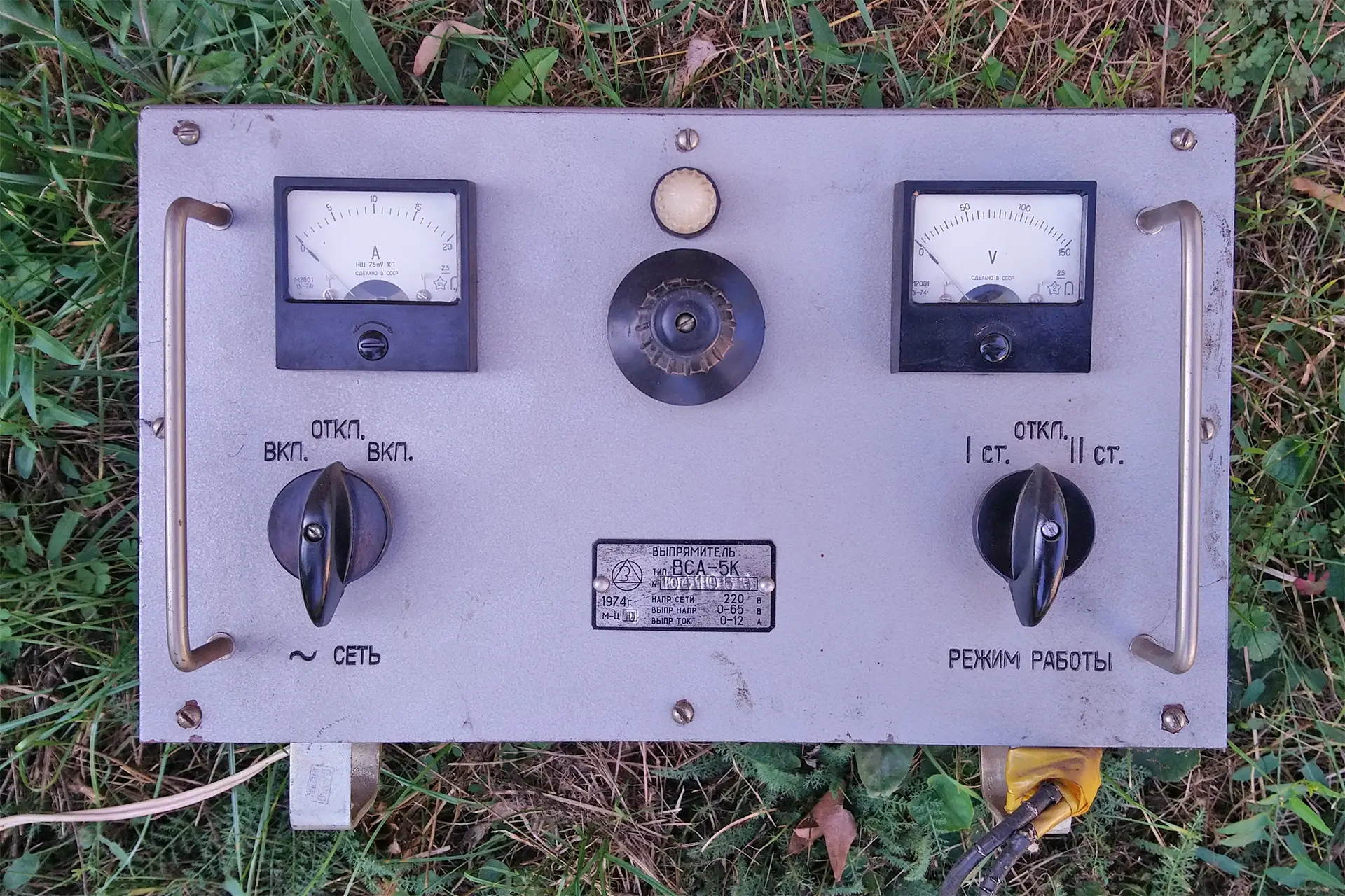
The ВСА-5К is designed for charging lead-acid batteries in cars and trucks and can also be used as a DC power supply. It doesn’t include an output buffer capacitor (so there’s nothing to dry out), but this also means it delivers a pulsating DC current. The output voltage is more or less continuously adjustable between 0 and 65 V, with a maximum output current of 12 A.
Technical Specifications
- Power supply: 127/220 volts, 50–60 Hz
- Rectified voltage: 0 to 65 volts, in two ranges
- Rectified current: up to 12 amperes
- Operating temperature range: –25°C to +35°C
- Relative air humidity: up to 80%
- Atmospheric pressure: 720–780 mmHg
- Vibration: up to 4 g acceleration in the 20–80 Hz frequency range
- Repeated shocks: up to 15 g, lasting 5–10 ms
- The air must be free of acid and alkali vapors
- Maximum operating conditions:
- Ambient temperature: +25°C to +40°C, and +35°C to +50°C
- Relative air humidity: 80% to 90% at +25°C
- Reduced atmospheric pressure: down to 480 mmHg
- Dimensions (W×D×H): 350 × 260 × 232 mm
- Weight: 24 kg
- Protection against electric shock: grounding (Soviet NNYO/ANB standard – basically: “Don’t touch it and it won’t zap you.”)
Operation
A schematic diagram of the ВСА-5К is shown in the figure below. I grabbed this drawing from a Russian website—it’s not entirely accurate, since the device was manufactured in several different versions. This particular diagram shows the single-switch version, whereas ours has two rotary switches. That aside, the diagram is more or less representative of reality and clearly shows the essential workings.

The transformer in the ВСА-5К device can be powered from a 127 or 220 V AC mains supply. The voltage selection is made by changing a jumper on a terminal block located under a screw-on cover on the left side of the unit. This is also where the HL1 indicator lamp is connected, which shows whether the device is switched on (note: the bulb operates on just 26 V).
The unit is switched on using the left-hand switch labeled ~ СЕТЬ (~ MAINS):
- ВКЛ. (= ВКЛЮЧЕНИЕ, ON)
- ОТКЛ. (= ОТКЛЮЧЕНИЕ, OFF)
This is a double-pole switch that breaks both lines of the mains input—and, interestingly, also disconnects the secondary side (more on that later).
Note: According to the schematic, this is one half of the SA1 switch, but in our version it’s a separate switch located before fuse F1 (so that dashed line representing a mechanical link between the two SA1 sections doesn’t apply here). Regardless of the direction it’s turned, the center position is OFF; turning left or right switches it ON.
Mains voltage passes through the switch and fuse into the T1 transformer, which has an adjustable secondary voltage. This is a rather curious component: it’s similar to a variable toroidal transformer, but it’s not an autotransformer (i.e., the primary and secondary sides are electrically isolated), and it’s not circular but linear. Each of the two secondary windings has a sliding brush on the outside, which is moved by a central knob (the unlabeled one) via a lead screw. As the brushes move, the output voltage changes.
The right-hand switch, labeled РЕЖИМ РАБОТЫ (OPERATING MODE), also has three positions. In the center position it’s ОТКЛ., meaning OFF, but unlike the schematic, it does not break the primary side—only the secondary. There was a version with a single combined switch, and that’s the one shown in the schematic I found, where this switch did cut the primary circuit as well. But in my ВСА-5К, the two switches are separate.
The meaning of the rather cryptic I СТ. and II СТ. positions is the voltage range:
- I СТ.: 0…33 V
- II СТ.: 32…65 V
The switch toggles between different transformer windings, producing either 0–50% or 50–100% of the output voltage. The winding is designed so there’s at least a 0.5 V overlap between the two ranges.
It’s important to note:
- Voltage adjustment from 0 to 33 V is clockwise
- Voltage adjustment from 32 to 65 V is counterclockwise!


The transformer’s voltage is fed to the VD1…VD4 Graetz bridge rectifier. Earlier versions of the device (such as the much taller, 24 A-rated ВСА-5) used selenium rectifiers. On Russian websites, you can find photos of upgraded versions where the original selenium rectifiers were replaced with modern silicon diodes.
The ВСА-5К, however, already came from the factory with silicon diodes. According to a datasheet I found, the Д245А (D245A) diodes are rated at 300 V / 10 A. As a rule of thumb, I usually recommend using diodes rated for at least three times the actual load current in a bridge rectifier—so ideally, this would call for 30 A diodes. Nowadays that’s easy, but back then, such components were rare. It’s likely that the Russian engineers installed 10 A diodes on paper, but real-world experience shows they can handle 12 A just fine.
If you ever need to replace them, I recommend types like 1N3765 to 1N3768 (rated at 35 A / 700–1000 V, roughly €60 apiece). If one fails, replace all four diodes, even if only one appears to be bad!
The VZ1 surge protector protects the diodes from transient overvoltages that may occur when switching the transformer on or off. The ОСН90-420-2 (OSN90-420-2) is mounted on the same Bakelite piece that holds the sliding contacts on the transformer windings (you can see it in the photo above). I found that it’s a 90 V / 0.5 A selenium suppressor, supposedly self-healing. If it fails, a suitable replacement would be the P6KE68CA bidirectional TVS (transient voltage suppressor) diode.
On the output side, there’s the PA1 ammeter, rated up to 20 A, and the PV1 voltmeter, which goes up to 150 V. The ammeter is paired with a shunt resistor (Rш1), which in this unit is not located near the meter itself, but rather mounted on the bottom side of the chassis.
The SA1 switch also disconnects the secondary circuit and the ammeter in the OFF position. The voltmeter, on the other hand, is always connected to the output terminals—so when the device is off, it shows the open-circuit voltage of the connected battery.
Much later, after the fall of the Soviet Union, a new version called the ВСА-5КМ appeared. It was rated at 36 V / 24 A, and instead of a fuse, it used a proper circuit breaker for overcurrent protection. The output terminals were also upgraded to proper screw or banana plug connectors.
In the old ВСА-5К, however, the output is located on the right-hand side, behind a screw-on cover, just like the input terminal block on the left. Wires are connected to these terminal blocks using screw terminals, essentially fixed in place, hidden beneath the housing—and exit through the open bottom of the enclosure.


Commissioning
The original manual outlines standard safety precautions. In short:
- The device must be placed in a dry, heated, and well-lit room.
- Do not use acids, acetone, or other corrosive vapors in the room where the device is located.
- Do not place the device near heat-emitting objects (e.g., radiators or heaters).
- Do not cover the ventilation openings, and don’t place the device flush against a wall! Proper ventilation must be ensured for adequate cooling.
- The operator must be properly instructed…
If the device has been stored or transported at temperatures below +5°C, it must be thoroughly dried out before switching it on!
According to the manual, you should check the condition of the wiring, controls, etc., before use. Interestingly, it says there is you need to know the actual mains voltage before connecting the device (which probably made sense in the USSR or occupied regions where voltage standards weren’t always reliable). It suggests setting the jumper to the higher voltage (220 V), then connecting to the power supply and switching on. Turn the voltage adjustment knob to the maximum, and check the reading on the voltmeter. In the case of the ВСА-5К, it should read 65 V (for the ВСА-111, it would be 80 V).
Important: The metal housing must be grounded before connecting the unit to the electrical network!
The original power cord has only two wires—there is no protective ground conductor. Grounding must be provided via a separate wire, bolted to the metal housing of the unit (there is a hole for this on one of the rear legs).
Usage
If the battery is discharged, it should be charged according to the battery manufacturer’s instructions. According to the manual:
- Make sure the device is disconnected from the mains! (It’s enough to set the left-hand switch to the middle ОТКЛ. position—this disconnects both the mains and the secondary circuit.)
- Connect the battery with correct polarity!
- Check the voltage on the voltmeter!
- Set the voltage adjustment knob to the lowest setting!
(Note: This won’t be reflected on the voltmeter, which shows the battery’s open-circuit voltage. Also, be aware that the minimum setting is in a different position depending on whether you’re in the I СТ or II СТ range!) - Turn on the power!
(First the left-hand switch—the indicator lamp will light up—then the right-hand switch to I СТ or II СТ, depending on the battery’s rated voltage.) - Turn up the voltage until the desired charging current—according to the battery specs—starts to flow. Charge the battery, then switch off the device and disconnect the battery.
⚠️ Warning: During charging, make sure the battery current does not exceed 12 A (in the case of the ВСА-5К)!
The above notes in parentheses are mine.
In my opinion, contrary to the original manual, it’s better to first select the proper voltage range using the right-hand switch, based on the battery’s nominal voltage. For 12 V car batteries, that would be the I СТ position, and you can leave the switch there permanently.
Next, with the device powered on, set the voltage slightly below the nominal open-circuit voltage of a fully charged battery. In principle, there’s no need to turn the voltage knob all the way down to zero—but it’s important that the starting voltage be low enough to prevent an excessive current surge when the charging begins. However, this requires some experience, and also assumes you’ve verified that the battery isn’t shorted. If you’re unsure, it really is safest to start from zero. Once the voltage is adjusted, switch the device off using the left-hand switch (ОТКЛ.), then connect the battery.
Always check the voltmeter before switching the power back on—it can tell you a lot. (For example, the reading should never be zero—not even with a dead battery. If it is, suspect a short circuit!)
If the unit sparks while turning the voltage knob, disconnect the power, unplug the battery, remove the cover, and clean the top of the transformer and the sliding brushes—dust is likely the cause.
According to the manual, the brushes should be operated for no more than 3 hours continuously, whether under load or not.
If the ambient temperature is between +35°C and +50°C, you should reduce the load by 20%.
Mains voltage may fluctuate, but must not exceed +10% of the nominal value. If it does, reduce the load by 10%.
(At the time, the nominal mains voltage was 220 V in the USSR.)
Maintenance
The top of the transformer’s secondary winding, the sliding contacts, and the diode heatsinks should be inspected regularly (e.g., monthly) and blown clean with compressed air. If neglected, the voltage regulator may start to spark! Dust buildup on the secondary coil can also cause the brushes to twist out of alignment and the threaded shaft to loosen.
Check the condition of all screws, nuts, and fasteners every six months.
When charging new batteries (or regenerating alkaline cells), a variable series resistor should be connected in series with the battery to limit the charging current.
If the device is operated for extended periods at around 98% humidity, or at temperatures below +25°C, its components may begin to rust. To prevent this, the manual recommends applying a coating of technical petroleum jelly or other anti-corrosion compound to the metal parts.
(That last part is very Soviet, isn’t it?)
Safety
- Always disconnect the device from the mains before performing any repairs!
- When installing replacement diodes, do not apply more than 1 kp (kilopond) of force to the insulated diode lead!
- Do not overtighten the nuts—the torque must not exceed 6 kp/cm or 15 kp/cm, depending on the specific part.
- When soldering diodes, the temperature must not exceed 250°C, and the soldering time must be no longer than 3 seconds!
- Do not use acid-based flux for soldering!
Characteristics of Automotive Lead-Acid Starter Batteries
Modern automotive lead-acid starter batteries are almost all “maintenance-free,” meaning there’s no need to monitor or refill the electrolyte (acid).
In older batteries, the acid level and density had to be checked regularly, and distilled water had to be added to compensate for losses due to evaporation. These batteries were sold dry, and during commissioning, the user had to fill them with acid and then charge them electrically using a battery charger. The acid density had to be adjusted to 1.285 kg/dm³ at 20°C (equivalent to 32 °Bé), using a hydrometer. Tables were available for other temperatures, but this value was appropriate for 15–25°C.
After filling to the correct level, the battery had to be charged for 24 hours, then left to rest for 4–6 hours. After resting, the acid level was checked and topped up if needed, and the battery was charged further at half the previous current until the total charge input reached 3 to 4 times the rated capacity. Finally, the acid level and density were checked again.
⚠️ A battery that has already been commissioned must never be stored in a discharged state!
Later, so-called “dry-charged” batteries became available. These did not require electrical charging—only the appropriate acid had to be filled in. After resting for 4–6 hours, the acid was checked and balanced, and the battery was ready for use.
Today’s maintenance-free batteries are sold fully charged and ready to use. You simply install them, and you’re good to go. There’s no need to check electrolyte levels or top up, and often it’s not even possible, since the batteries are fully sealed—an undeniable advantage.
However, batteries are sensitive to both overcharging and deep discharge. They must not be stored discharged, or they will deteriorate. A discharged battery must be recharged within 24 hours.
During overcharging, explosive gases (hydrogen and oxygen) are produced in the battery.
Always read the battery’s documentation. Never exceed the maximum charging current specified by the manufacturer! Once the cell voltage reaches 2.4 V, the charging current must be reduced to the manufacturer’s recommended level.
Modern batteries often include built-in recombination catalysts (typically palladium), which convert the evolving gases back into water (reducing water loss as well). These catalysts are designed for normal operating conditions. In cases of severe overcharging—which can easily happen if the ВСА-5К is not used carefully—more gas may be produced than the catalyst can handle.
In such cases, the battery’s safety valves release the excess gas, usually preventing the battery from exploding. However, the gases can accumulate in the room and pose a serious explosion hazard! For this reason, batteries should only be charged in well-ventilated areas, especially when using this charger!
⚠️ Intense gas formation can also cause mechanical damage to the battery plates!
Since this charger contains no electronics whatsoever to monitor or control the charging process, it’s up to us to pay close attention! This requires a basic understanding of battery characteristics. Here’s a quick overview for a single cell, and for a 6-cell, 12 V car battery:
| Parameter | Per Cell | 12 V Battery |
|---|---|---|
| Minimum allowable voltage | 1.75 V | 10.5 V |
| Nominal resting voltage (fully charged) | 2.125 V | 12.75 V |
| Onset of gas formation | 2.4 V | 14.4 V |
| Final charging voltage | 2.7 V | 16.2 V |
| Internal resistance (1) | ~0.02 Ω | – |
| Rated capacity (2) | – | 20 h (at 25°C) |
(1) Internal resistance increases with discharge and with decreasing temperature, and also rises with higher discharge current. For a depleted battery, it can reach 0.04–0.05 Ω.
(2) The storage capacity is specified in Ah for a given battery, but the rated discharge time is based on a 20-hour discharge at +25°C. Capacity is highly temperature-dependent:
- At +40°C, it reaches ~110% of nominal
- At 0°C, it drops to 75%
- At –10°C, to 60%
- At –20°C, to 40%
During constant voltage charging (as this charger provides), the relationship between charging current and terminal voltage is illustrated in the diagram below.
It’s very important to understand these curves when using this type of charger!

The charging current should be selected so that it is approximately 1/10 to 1/12 of the battery’s nominal capacity (measured in Ah), expressed in amperes. For example, for a 60 Ah battery, 60 ÷ 10 = 6 A and 60 ÷ 12 = 5 A—so the charging current should be between 5 and 6 A. In our case, this can be achieved by adjusting the voltage control knob until the ammeter shows the desired current.
A significant change in the charging process occurs only after roughly three-quarters of the charging time has passed. If a fully discharged battery is charged at C/10, this point comes about 8–9 hours after charging begins. At this stage, the voltage rises to approximately 2.4 V per cell, and gas formation begins. At this point, the battery is only charged to 75–80% of its full capacity, so charging must continue.
For modern batteries, instead of continuing with constant voltage charging at C/10 to C/12, it is recommended to switch to constant current charging at C/20 to reduce gas evolution. Automatic chargers take care of this by themselves, but with the ВСА-5К, we need to handle it manually!
At this stage, the charging current will start to drop on its own, but if the current is not at the correct level, adjust the voltage accordingly. For instance, for a 60 Ah battery, the current should be about 60 ÷ 20 = 3 A.
Once the cell voltage reaches 2.4 V (which equals 14.4 V terminal voltage for a 12 V battery), the charging should continue at reduced current. The cell voltage increases rapidly and soon reaches 2.7 V per cell (i.e., 16.2 V terminal voltage for a 12 V battery). At this point, the voltage stabilizes and no longer increases.
Charging is considered complete when the terminal voltage has remained unchanged for at least two hours. This typically occurs around 20 to 28 hours after charging begins. If you don’t stop it at exactly the two-hour mark, it’s not a disaster—but continuing to charge beyond this point can severely reduce the battery’s lifespan.
Also, monitor the battery temperature during charging. It should not exceed 45°C!
Some Tips
You can get a good indication of an unknown battery’s condition by checking its electrolyte density and terminal voltage:
| Battery Charge Level | Resting Cell Voltage | Electrolyte Density |
|---|---|---|
| 0% (discharged) | 1.80 V | 1.12 kg/dm³ (16 °Bé) |
| 50% (half charged) | 1.94 V | 1.20 kg/dm³ (24 °Bé) |
| 100% (fully charged) | 2.10 V | 1.285 kg/dm³ (32 °Bé) |
The higher the charging current, the less likely the battery will reach its rated capacity.
To reduce the charging current, the original ВСА-5К manual recommends placing a variable resistor in series with the battery—especially for new batteries. However, such high-power wirewound resistors are rare these days (unless you have access to an old school physics lab), so here’s a simple trick that can be used with virtually any battery and constant-voltage charging: use an incandescent light bulb.
A 12 V headlight bulb (just one filament of a 40/45 W bulb—either one will do) wired in series with the battery provides a suitable charging current and also works as a visual charge indicator:
- If the bulb lights up when power is turned on → the battery needs charging.
- If the bulb glows dim red → the battery is fully charged, no further charging is needed.
- If the bulb doesn’t light at all → either the power is off, the wires aren’t connected properly, or the battery is faulty.
- If the bulb shines brightly → the battery is more than 50% discharged and is being charged.
- If the bulb starts bright and gradually dims to a dull red glow → the charging process is proceeding normally and has completed.
- If the bulb stays bright for over 30 minutes without dimming → the battery is deeply discharged and faulty, and is not accepting charge.
A headlight bulb works well for 40–60 Ah lead-acid automotive batteries, but with care, this method can also be used to charge NiCd batteries, which require constant-current charging.
For smaller batteries, a 12 V / 3 W parking light bulb can be used.