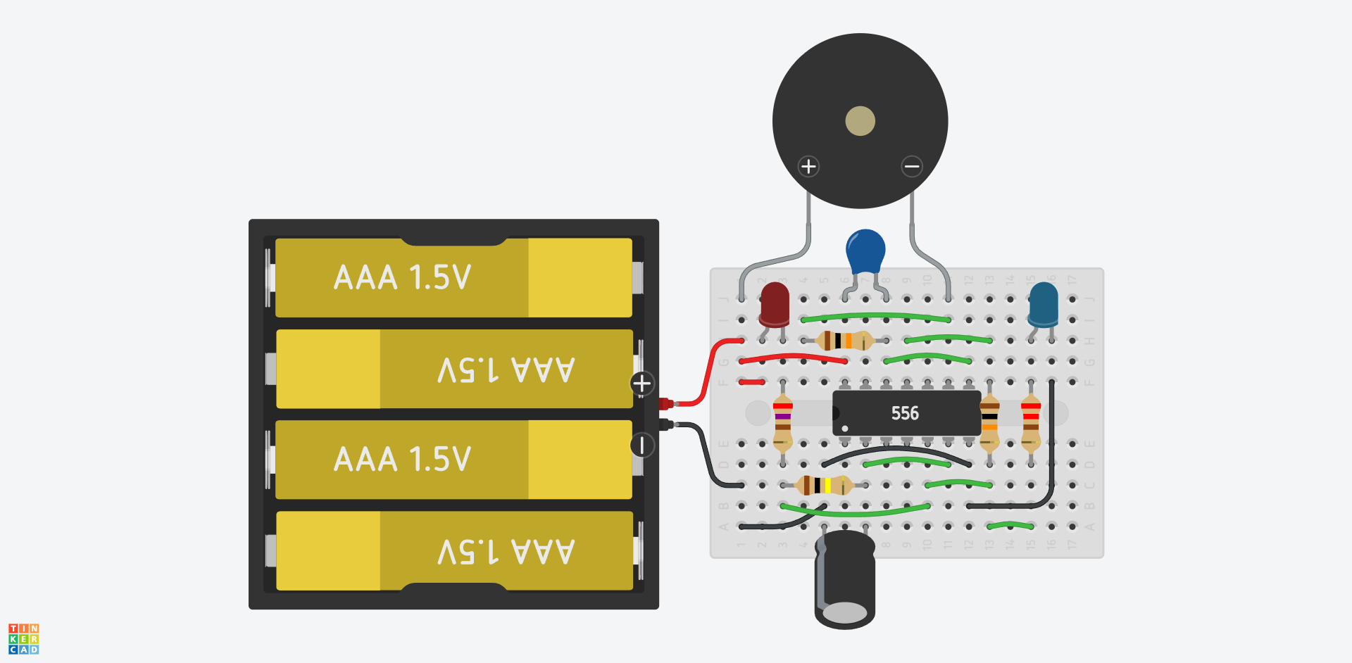
A popular variant of the well-known NE555 timer IC is the NE556, which contains two timers. With this IC, you can build a simple siren. This siren alternates between two tones, similar to old police car sirens, while also flashing a blue and a red LED. You can test the circuit in Tinkercad:
👉 https://www.tinkercad.com/things/lsxjw2LzvA7-police-siren
Note during assembly:
C2 is an electrolytic capacitor, which is polarized — its orientation matters. The side marked with a white stripe is the negative terminal and must be connected to the negative pole of the battery!
What do you need?
| Name | Quantity | Component |
|---|---|---|
| Mini Breadboard | 1 | BB-170 prototype board |
| U1 | 1 | NE556 dual timer IC |
| D1 | 1 | Blue LED |
| D2 | 1 | Red LED |
| C1 | 1 | 100 nF ceramic capacitor |
| C2 | 1 | 4.7 μF, 25 V electrolytic capacitor |
| R1, R2 | 2 | 10 kΩ, 0.6 W resistors |
| R3 | 1 | 100 kΩ, 0.6 W resistor |
| R4 | 1 | 220 Ω, 0.6 W resistor |
| R5 | 1 | 270 Ω, 0.6 W resistor |
| PIEZO | 1 | Piezo speaker |
| Bat1 | 1 | 4 × AAA battery holder + 4 pcs 1.5 V batteries (or 1.2 V rechargeable) |
How does it work?
The NE556 is a 14-pin IC containing two precision timers, each functionally equivalent to an NE555. It can be used in a variety of applications. (You can read more about the NE555 here.) You can download the NE556 datasheet online; the pin functions are shown in the diagram below:

The IC requires a power supply, which in this case is provided by 4 AAA batteries. The positive terminal connects to pin 14 (Vcc), and the negative terminal connects to pin 7 (GND).
The outputs of the two timers are pins 5 and 9, each connected internally to a flip-flop. Each flip-flop is driven by two comparators, with their Threshold and Trigger inputs connected together. If the voltage at the Trigger/Threshold input exceeds 2/3 of the supply voltage, the flip-flop output switches low (about 0 V). If the input drops below 1/3 of the supply voltage, the output switches high (close to Vcc).
Each timer has a capacitor connected to its input, which charges and discharges through resistors, depending on the output voltage. When the output is high, current flows through the resistor into the capacitor, gradually charging it. When it reaches 2/3 of the supply voltage, the flip-flop toggles, and the output goes low. Then the capacitor discharges through the resistor toward the output, until the voltage drops below 1/3 of Vcc — the flip-flop toggles again, and the cycle repeats. The frequency of this cycle depends on the resistor and capacitor values. Larger resistors and capacitors make it slower.
The first timer uses a 4.7 μF capacitor and a 100 kΩ resistor, so it oscillates slowly. This controls the LED blinking. Its output is also connected through a 10 kΩ resistor (R2) to the Control Voltage input of the second timer.
The second timer uses a 100 nF ceramic capacitor and a 10 kΩ resistor, producing a high-frequency oscillation (audio range). Its Control Voltage input is influenced by the output of the first timer via R2, which modulates its switching thresholds — this causes the tone pitch to vary.
Try this:
Attach an oscilloscope to the 100 nF capacitor and observe how its voltage changes over time!

