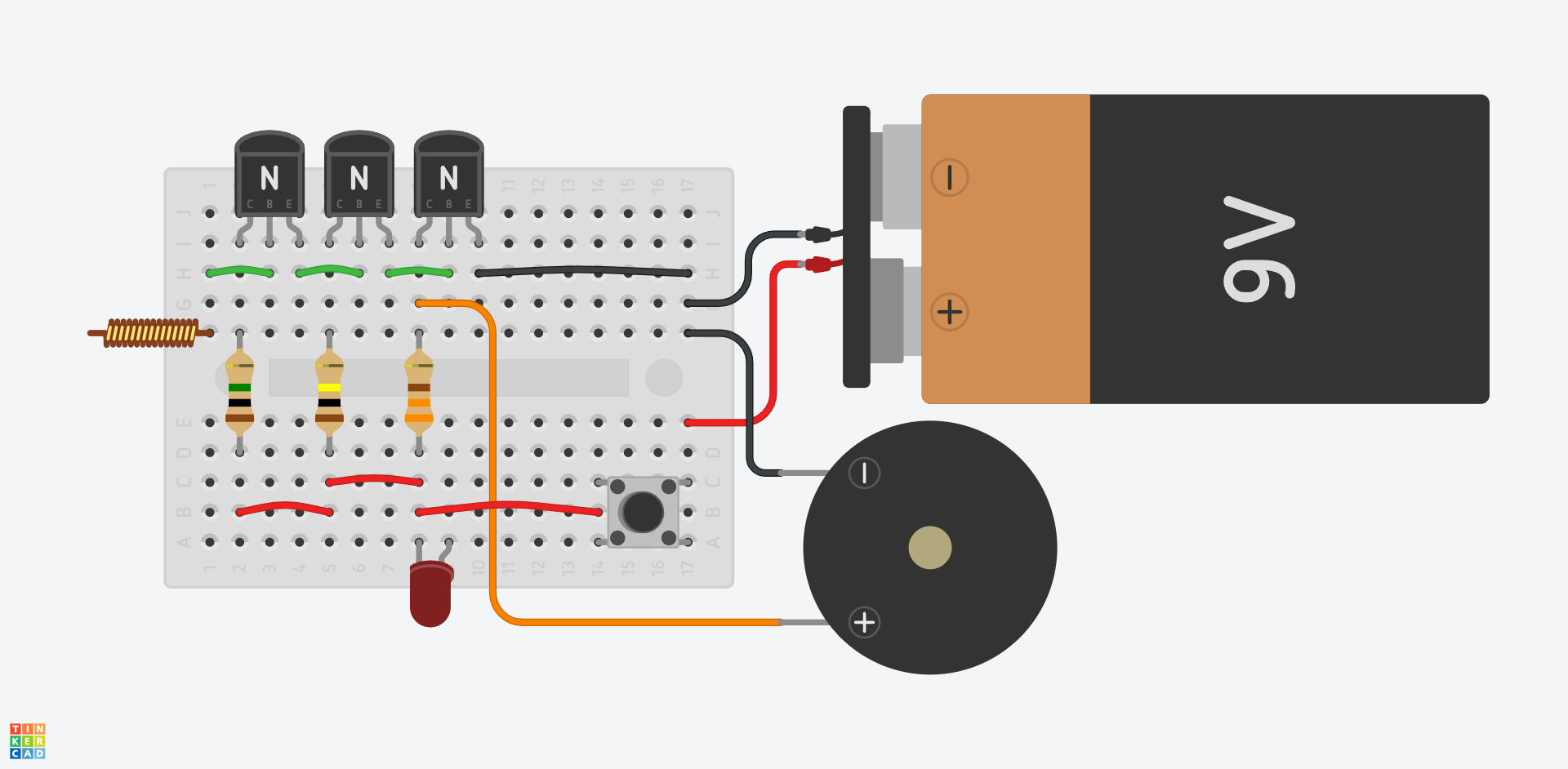
This circuit is a simple, contactless wire / mains voltage detector. It can detect 230 V mains wiring from a distance of 10–15 cm, indicated by a red LED and a buzzing sound. You can find the circuit in Tinkercad:
👉 https://www.tinkercad.com/things/cZa2iaSgAAG-wire-tracer
The L1 coil is a self-supporting air-core coil. It can be made from a 10–12 cm long, approx. 0.5 mm diameter stiff insulated wire, loosely wound around a rod with a diameter of about 3–5 mm (e.g. a wooden skewer), which is then removed. The exact size and number of turns are not critical.
Piezo 1 is a piezo buzzer with a built-in driver circuit, meaning it will produce sound when a DC voltage is applied.
Power supply: 9V 6LR61 alkaline battery. Maximum current draw is 20 mA, and the device only consumes power when the pushbutton is held down, which conserves the battery.
Warning! This circuit is intended for experimental and educational purposes only. It must not be used for electrical installation or construction work! Children may use it only under adult supervision. The circuit must never be connected directly to mains voltage or touched to live wires—this is strictly prohibited and life-threatening! The device is intended only for detecting insulated wires inside walls. It is not a measuring instrument and must not be used for official measurement or inspection. The designer assumes no responsibility for any accidents, damages, or consequences resulting from the use of this product. Use at your own risk!
Required components
| Name | Quantity | Component |
|---|---|---|
| Mini breadboard | 1 | BB-170 prototype board |
| T1, T2, T3 | 3 | Any general-purpose NPN transistor with h21e ≈ 150…250, e.g. BC237B, BC547B, BC557B |
| R1 | 1 | 1 MΩ resistor |
| R2 | 1 | 100 kΩ resistor |
| R3 | 1 | 330 Ω resistor |
| D1 | 1 | 5 mm red LED |
| PIEZO1 | 1 | Piezo buzzer with built-in oscillator |
| L1 | 1 | Coil antenna (see text) |
| S1 | 1 | Pushbutton |
| BAT1 | 1 | 9V battery clip |
| BAT1 | 1 | 9V battery |
How it works
The wire acts as an antenna, picking up energy from the AC electric field emitted by live mains wiring. A very small base current flows into transistor T1, triggering its collector current. The induced voltage is amplified by the three cascaded transistors, producing enough current to drive the LED and buzzer.
The collector current (IC) equals the base current (IB) multiplied by the current gain: IE ≈ h21e · IB. The current gain (h21e) is a datasheet value, though it may vary even between identical transistor types. In this circuit we assume h21e ≈ 200 for each transistor. The emitter current is: IE = IC + IB,, but since IC ≫ IB, we can approximate IE ≈ h21e · IB
Because the three transistors are cascaded: T2’s base current comes from T1’s emitter; T3’s base current comes from T2’s emitter. So:
IB.T2 = IE.T1
IB.T3 = IE.T2
Which gives:
IE.T2 ≈ h21e · IB.T2 ≈ h21e · IE.T1 ≈ h21e · h21e · IB.T1
IE.T3 = h21e · IB.T3 ≈ h21e · IE.T2 ≈ h21e · h21e · h21e · IB.T1 ≈ (h21e)³ · IB.T1
If h21e = 200, then (h21e)³ = 200 · 200 · 200 = 8.000.000, meaning the three transistors together amplify the current eight million times. To fully light the LED, approx. 20 mA is needed. That requires only 2.5 pA (picoamperes) of base current at T1—just eight-millionth of 20 mA. This minuscule current can easily be picked up from the electric field around live wires.
Tip
Your home is full of electric fields from appliances and mains wiring—this is often referred to as “electrosmog.” It includes both low-frequency (from power lines and devices) and high-frequency (radio, TV, mobile phones, Wi-Fi) components.
If the circuit is too sensitive, it may detect all sorts of electric fields. In that case, it can be used as an electrosmog detector. If you want to use it as a wire finder, consider replacing one of the transistors with a lower-gain version.
Bonus tip: Finding a faulty bulb in an old-style Christmas light string
The device can also help identify a burnt-out bulb in a traditional incandescent Christmas light string (not LED). Here’s how:
- Plug the light string into a socket.
- Use the device to probe near the wire segment between the first two bulbs.
- The device will either buzz/light up or remain silent.
- Move to the next segment and repeat.
- Continue until you find a bulb where the device reacts on one side but not the other—that bulb is faulty!
- Unplug the string and replace the bad bulb.
Caution: Only approach the insulated wires with the detector. Do not touch the bulbs, their sockets, or the plug! Always unplug the lights before replacing a bulb. Sometimes multiple bulbs may be burnt out. This method finds the first one. Continue in the direction where the detector previously showed no signal to find the next.