This circuit is a simple flasher that produces strong and short flashes. If you already know how a transistor works, you’ll have no trouble understanding how this thing operates. You can find the circuit on Tinkercad here:
👉 https://www.tinkercad.com/things/jn4ZX0OA4qi-flashing-light
Although it works in a very simple way, this circuit actually exceeds the capabilities of Tinkercad’s circuit simulator. Even if you start the simulation, nothing will happen—yet the circuit does work in real life! This is a good example of why you shouldn’t always take what a simulator shows at face value.
What do you need?
| Name | Quantity | Component |
|---|---|---|
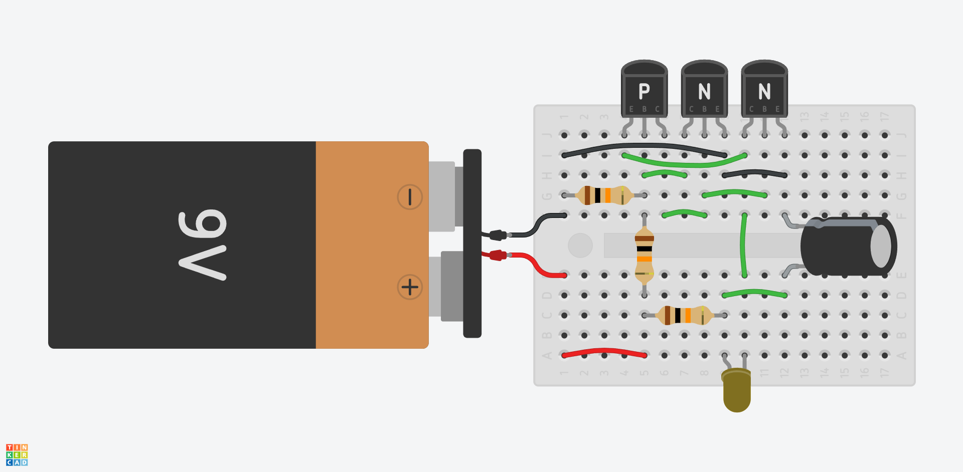
| Mini Breadboard | 1 | BB-170 prototyping board |
| T1 | 1 | PNP transistor (e.g., BC557 or similar) |
| T2, T3 | 2 | NPN transistor (e.g., BC547 or similar) |
| D1 | 1 | High-brightness yellow LED (e.g., EVL-080-307-YEL) |
| R1, R2, R3 | 3 | 10 kΩ resistors |
| C1 | 1 | 100 μF, 16 V polarized capacitor |
| BAT1 | 1 | 9V battery clip connector |
| BAT1 | 1 | 9V battery |
How does it work?
This circuit works by slowly charging the C1 capacitor, then discharging it suddenly through the LED once it reaches a certain voltage. The result is very bright but brief flashes, with longer pauses in between.
A bipolar junction transistor (BJT) is a semiconductor device mainly used for amplification or switching in electronic circuits. There are two types: NPN and PNP, depending on how their material structure is built. This circuit uses both types.

A transistor has three pins: base (B), emitter (E), and collector (C). Many types and packages exist; here, we use low-power types in small black plastic cases known as TO-92, where the pin order is the same for NPN and PNP types.
The operation of a BJT is determined by the flow of electric charge between the emitter, base, and collector. When the voltage between the base and emitter exceeds the base-emitter threshold voltage, current starts to flow into the base. For silicon transistors, this is typically around 0.65 V. In an NPN transistor, the base must be positive relative to the emitter (in a PNP, the opposite). This base current causes the transistor to “turn on”, and collector-emitter current flows, which is proportional to the base current (Ic = β·Ib, where β ≈ 100…200). This is the transistor’s current gain, and it allows the transistor to amplify current.
In this circuit, however, we use the transistors as switches, meaning they turn on and off very quickly.
When the circuit powers on, the 100 μF C1 capacitor starts charging through the 10 kΩ R3 resistor. At this stage, the T1 PNP transistor is off, so the two NPN transistors (T2 and T3) get no base current either. Meanwhile, resistors R1 and R2 hold T1’s base at about 4.5 V (half of the supply voltage).
Once the capacitor charges to around 5.2 V, the emitter of T1 (connected to the capacitor via the LED) becomes positive enough compared to the base for T1 to turn on. As T1 turns on, T2 and T3 receive base current and also turn on.
When T2 turns on, it pulls T1’s base down toward the battery’s negative terminal by bypassing R1. This means T1 gets an even stronger turn-on signal. This forms positive feedback, causing T1 (and thus T2 and T3) to switch on very rapidly.
With T3 on, current flows from the capacitor through the LED, and since there’s no current-limiting resistor, the current is very strong. The capacitor discharges almost instantly, producing a very bright flash of the LED.
Normally, LED current is limited using a resistor, but in this case, it’s not necessary because the high current lasts for a very short time. LEDs can usually handle current pulses up to 10× their rated continuous current if the pulse is brief enough.