Spotters, SWL (shortwave listening) enthusiasts, and amateur radio operators all enjoy listening to aircraft communications — and nowadays, even drone pilots find it useful to monitor air traffic. A good handheld airband transceiver easily costs well over a hundred thousand forints, whereas the device described here is dirt cheap by comparison. Of course, it’s not suited for serious tasks, but it’s perfectly adequate for monitoring nearby aircraft communications during an airshow, for instance. And that’s not a useless thing — especially if you’re aiming to take great photos.
At BURABU (the Hungarian amateur radio meetup), I came across a “DIY Airband Radio Receiver (AM 118–136 MHz)” kit. I decided to take a closer look and see what it could do — so I haggled the price down. The kit is available for around $20 from eBay, Amazon, and several Chinese and Hong Kong webshops. In Hungary, it’s also sold by HAM Bazár (Rádióvilág Kft., Budapest XIII, Dagály Street 11, 1st floor).
It’s a great little project even for beginners, and a good way to learn how a basic heterodyne AM receiver works.
The full civilian airband range spans from 108.000 MHz to 136.975 MHz. The lower portion (108.000–117.975 MHz) is reserved for NAV — that is, navigation — and isn’t very exciting to listen to. You’ll mostly hear VORs and ILS signals there. The actual conversations between pilots and air traffic controllers take place in the COM (communication) portion, from 118.000 MHz to 136.975 MHz. All civilian aircraft — not military — operate strictly within this frequency range. Their onboard radios can’t use any other bands. Military airband communications take place at higher frequencies, and their channel allocations are not public. Much of it is encrypted anyway.
Civil aviation communications, on the other hand, are unencrypted and freely receivable by anyone. It’s important to note, however, that only authorized individuals are allowed to transmit. Just listening is perfectly legal, but interfering with air traffic control or aircraft communications is a serious criminal offense that could even land you in prison (according to Hungarian Penal Code §233: Endangering rail, air, or water transport).
You can download the full frequency allocation from the National Media and Communications Authority (NMHH). Aircraft communications are extremely concise, based on a laconic and standardized protocol, using English radiotelephony. This is mandatory even if both parties are native Hungarian speakers. So you’ll rarely hear any Hungarian on the air (maybe an occasional “sziasztok”), and definitely no chitchat.
In Hungary, air traffic control is handled by HungaroControl. Above 9,500 feet, airspace is monitored by en-route or area controllers (ACC – Area Control Service). Several people work simultaneously, with the airspace divided into sectors and zones based on function and controller workload. You’ll find the sector-specific frequencies in the frequency table.
A notable frequency is 127.400 MHz, known as VOLMET, which continuously broadcasts meteorological information to aircraft. Since this little radio has no tuning scale, it’s a handy reference point — you’ll know you’ve hit it when you hear the endless weather-robot lady talking.
Larger airports like Budapest (Ferihegy), Kecskemét, and Szolnok have a designated APP (Approach Control Service) area, supervised by a separate control unit. They manage inbound and outbound aircraft, as well as lower-flying traffic handed over from the ACC. The upper boundary of the Budapest APP zone is 19,500 feet (≈5,950 meters), with a horizontal coverage of about 100–150 km. You can listen in on them at 122.975 MHz and 123.850 MHz.
The immediate airport area and the runway are monitored by the TWR (tower), which takes over inbound traffic and hands off outbound traffic to APP. The tower also oversees planes in the traffic pattern, which are often visible by eye. Ferihegy tower transmits on 118.100 MHz.
Ground movements outside the runway — such as taxiways, parking stands, and aprons — are handled by GND (ground control), heard on 121.910 MHz.
121.500 MHz is the international emergency frequency, and 123.100 MHz is used by search and rescue (SAR) services. Normally, you won’t hear anything on these channels. If a pilot is already in contact with a controller (ACC, APP, TWR, or GND), they are expected to continue using that frequency in an emergency — unless instructed otherwise. The international emergency channel is only used when no other contact is possible, e.g., over the ocean. It is constantly monitored by several civilian and military stations, and by other aircraft en route. Some radios are designed to automatically switch to this frequency in emergencies, helping the pilot act quickly under pressure.
If you’re hoping to catch some dramatic MAYDAY calls, don’t tune in to 121.5 MHz — the action happens on the APP frequencies! But if you do hear a “MAYDAY,” look up — just to be safe. Or so you can at least see the thing that might put you on the evening news.
Receiver Description
As is often the case with many Chinese kits, the instructions are either missing or poorly translated. This kit came with a photocopied English manual — essentially the same content as the PDF version you can (barely) find online, just in a lower-quality format.
According to the manual, the receiver is designed to monitor communications between aircraft and control towers, “within a radius of up to 190 km with a suitable antenna.” The reality is — that suitable antenna really matters. With a small whip antenna, you can typically pick up approach control and aircraft takeoffs/landings from Budapest Airport (Ferihegy) from about 4–5 km away. With a λ/2 dipole stuck out a room window, that range goes up to around 15–20 km — provided the antenna has line-of-sight to the transmitter (e.g. the aircraft). If there’s a hill or building in the way, reception drops out. If you’re lucky with antenna placement, you might catch aircraft at distances of 70–80 km — though intelligibility will be right at the edge.
In my humble opinion, this little radio is most useful at airshows. In that setting, the lack of a frequency dial isn’t a big issue — you can quickly tune to the active local frequencies, since air traffic is fairly busy. Sensitivity isn’t a problem either, because you’re essentially “on site.”
The kit includes the following components:

Technical Specifications
- Power supply: 12 V DC
- Antenna: 50 ohm, unbalanced
- Reception frequency: 118–136 MHz, AM
- Typical current consumption: 30 mA
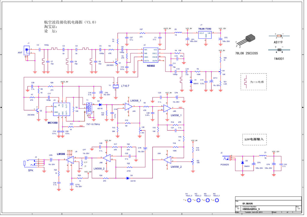
Circuit Diagram
The schematic included with the manual contains an error: the connection of the IF transformer is shown incorrectly. Below is the corrected version of the diagram:
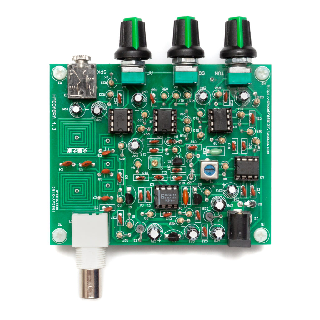
The PCB (Circuit Board)
The printed circuit board is a single-sided, through-hole design — nothing surface-mount here. It’s clearly made with beginners in mind: component markings are well laid out, there’s plenty of space between solder pads, and the layout is easy to follow. Still, some care is needed when identifying components: a few resistor and capacitor values are very close to each other, and it’s worth double-checking everything before soldering.
The printed circuit board is a single-sided, through-hole design, clearly aimed at beginners. There’s a silkscreen layer, but only position numbers are printed — no component values. This means that you’ll definitely need to keep the schematic and parts list close at hand during assembly.
Fortunately, the layout is relatively clean, and there’s enough space around most components for easy soldering. Still, caution is advised when identifying parts: some resistors and capacitors look deceptively similar, and it’s easy to mix them up without double-checking the values.
The IF transformer footprint is slightly inaccurate (as mentioned earlier in the schematic section), so a bit of mechanical adjustment may be necessary to make it fit properly.


How the Receiver Works
The antenna picks up the AM signal, which enters the circuit through connector J1. From there, it passes through capacitor C2 into a three-stage bandpass filter made up of capacitors C3–C9 and PCB-etched inductors. This bandpass filter selects signals in the 118–136 MHz VHF airband range. The selected signals are then amplified by transistor Q1 (2SC3355) by a factor of roughly 80–100.
Next, the signal enters U2 (NE602), a double-balanced mixer IC. This chip contains a Gilbert cell mixer and a built-in oscillator. Without diving too deep into the theory: the mixer produces an output that is proportional to the product of its two input signals. Using basic high school trigonometry, if both inputs are cosine signals with frequencies f₁ and f₂, the output consists of two new signals — one at f₁ + f₂, the other at f₁ – f₂.
The oscillator in U2 is tuned using a D1 varicap diode (BB910) and the W1 trimmer/potentiometer, theoretically covering a range of 128.7 to 146.7 MHz — that is, about 10.7 MHz higher than the desired reception frequency. The mixer outputs both the sum and difference frequencies, and the difference — 10.7 MHz — is the intermediate frequency (IF) used by the rest of the circuit.
The output from U2 is passed through Y1, a 10.7 MHz ceramic filter, which isolates the IF signal and suppresses the unwanted mixer products. The IF signal is then amplified by Q2, another transistor stage with a gain of about 80–100, and passed to pin 4 of U3 (MC1350), a dedicated IF amplifier IC. This chip includes an automatic gain control (AGC) function, which is regulated via the output of U4B.
Finally, the IF signal is fed through T1, the IF transformer, into the AM demodulator, consisting of D2, R10, and C18, which extracts the audio signal.
Notes:
- Pins 1 and 8 of the U3 IC are open-collector outputs. They drive the IF transformer in push-pull configuration, with the center tap of the transformer connected to the power supply, as shown in the corrected schematic.
- Diode D2 is marked as an “AS119” Schottky diode in the schematic. However, some users report better audio quality when using a germanium diode here (such as an AA119). Apparently, the Chinese manufacturer figured this out as well, because the kit actually includes a 1N60P, which is a germanium detector diode — and a good choice for this purpose.
- Diode D4 is also labeled “AS119” in the schematic, but the kit includes a 1N4148, a standard silicon diode, for this position.
- Resistor R15 is shown as 10 kΩ in the schematic, but some kits include a 4.7 kΩ resistor instead. Both values will work — the difference only slightly affects the gain of the U4B op-amp stage.
Audio Signal Path and AGC
The audio-frequency (AF) signal obtained after demodulation is further amplified by U4A and U5B (two op-amps inside two separate LM358 chips), and then finally by U6 (LM386), which drives either headphones or a small speaker.
(Don’t be confused if you see four op-amp symbols labeled as LM385 in the schematic — that’s clearly a mistake. The board actually uses two LM358 ICs, each containing two op-amps, so two chips = four amplifiers.)
U4B acts as a leaky integrator: it smooths the demodulated AF signal into a slowly varying voltage that is proportional to the signal’s amplitude. This control voltage is fed back to the AGC (Automatic Gain Control) input of U3 through resistor R11. The stronger the incoming signal, the higher the control voltage — and the AGC responds by reducing the gain of U3. This keeps the audio output within a comfortable listening range regardless of signal strength.
AGC is essential in airband receivers, since signal strength varies widely depending on how far the transmitter is. For example, the control tower might be booming in loud and clear, while a distant aircraft is barely audible. Constantly adjusting the volume manually would be impractical — AGC solves this by automatically evening things out.
Squelch Circuit
The receiver also features a squelch circuit, controlled by trimmer W2. U5A, one of the LM358 op-amps, functions as a comparator. The voltage set by W2 goes to the inverting input (pin 2), while the AGC voltage is fed to the non-inverting input (pin 3).
When the AGC voltage is lower than the squelch threshold, the comparator output (pin 1) drops to around 0.6 V, turning D4 on and effectively muting the signal at the input of U5B.
Once the AGC voltage exceeds the threshold set by W2, the comparator output suddenly jumps to about 6 V, turning D4 off and allowing the audio signal to pass through U5B.
If W2 is properly adjusted, the squelch effectively suppresses background noise and only allows actual transmissions to be heard.
Volume Control and Output
Volume is adjusted via W3, which, along with CP6, routes the AF signal to U5B and then on to U6 (LM386) — a popular low-voltage audio amplifier. Thanks to this design and the squelch system, the audio output has very low background noise, yet is still powerful enough to drive common small speakers or headphones with excellent clarity.
Assembly
Identifying the components based solely on the schematic and the silkscreened position numbers can be a bit tedious, so here’s a reference table to make things easier:
Before soldering, it’s always a good idea to start with the lowest-profile components (like resistors) and gradually work your way up to the tallest ones (electrolytic capacitors, connectors, etc.). It’s also highly recommended to check each component with a multimeter or component tester before installation — this is especially helpful in kits with inconsistent part labeling or substitutions.
And don’t forget to read the Modifications & Corrections section before you begin!
Parts List
| Component | Value | Marking / Color Code |
| Ellenállások | ||
| R1, R6, R11, R16, R29 (optional) | 1 kΩ | Brown-Black-Red |
| R2, R7, R9, R14, R17, R20, R24 | 47 kΩ | Yellow-Purple-Orange |
| R3, R27, R28 | 270 Ω | Red-Purple-Brown |
| R4, R8, R10, R15 | 10 kΩ | Brown-Black-Orange |
| R5, R18 | 100 kΩ | Brown-Black-Yellow |
| R12 | 1 MΩ | Brown-Black-Green |
| R13 | 33 kΩ | Orange-Orange-Orange |
| R19 | 4,7 kΩ | Yellow-Purple-Red |
| R21 | 3,3 kΩ | Orange-Orange-Red |
| R22 | 470 kΩ | Yellow-Purple-Yellow |
| R23, R25, R26 | 10 Ω | Brown-Black-Black |
| W1, W2, W3 | 10 kΩ potentiometer | 10K |
| Capacitors | ||
| C1, C16, C21, C22, C23, C24, C25, C26, C27, C28 | 100 nF | 104 |
| C2, C5, C6, C13, C17 | 1000 pF | 102 |
| C3, C4 | 2 pF | 2 |
| C7, C8, C9 | 47 pF | 47 |
| C10, C14 | 27 pF | 27 |
| C11 | 10 pF | 10 |
| C12, C15, C18, C19, C20 | 10 nF | 103 |
| C29 | 0.47 μF | 474 |
| Electrolytic Capacitor | ||
| CP1, CP2, CP5, CP8 | 100 μF | |
| CP3, CP4, CP6, CP7, CP9, CP10, CP11 | 10 μF | |
| Transistors | ||
| Q1, Q2 | 2SC3355 (NPN) | 2SC3355 (TO-92) |
| IC-k | ||
| U1 | 8V Voltage Regulator | 78L08 |
| U2 | NE602 RF Mixer | NE602/SA602 vagy NE612/SA612 |
| U3 | MC1350 IF Amplifier | MC1350 |
| U4, U5 | LM358 Dual Op-Amp | LM358 |
| U6 | LM386 Audio Amplifier | LM386 |
| Diodes | ||
| D1 | BB910 Varicap Diode | BB910 (TO-92) |
| D2 | 1N60P Detector Diode (germanium) | 1N60P |
| D3 | 1N4001 Power Diode | 1N4001 |
| D4 | 1N4148 Squelch Control Diode | 1N4048 |
| Other Components | ||
| Y1 | 10,7 MHz-es Ceramic Filter | L10.7 |
| L1 | Adjustable Inducto | |
| J1 | BNC Antenna Connector | |
| J2 | DC Power Jack (Center-positive) | |
| J3 | 3,5 mm-es Audio Jack | |
| Z1, Z2 | RF Choke | |
Assembly Instructions
As a general rule, always start soldering with the lowest-profile components and work your way up to the taller ones. Before installation, it’s a good idea to check all components with a multimeter or component tester.
Be sure to read the “Modifications” section before beginning!
Step-by-step assembly:
- Install all ceramic capacitors and C29 in their designated positions.
(Do not install the electrolytic capacitors yet!) - Install L1 (the adjustable inductor) and the IC sockets for U1–U4.
(Do not insert the ICs into the sockets yet!)
Pay close attention to the orientation — the small notch indicating pin 1 on the socket must match the corresponding mark on the PCB. - Install the 10.7 MHz ceramic filter (Y1).
Make sure pin 1 of the filter goes into the square-marked hole on the PCB. - Solder in all resistors.
(Do not install the potentiometers W1–W3 yet!) - Install the diodes D1–D4.
Orientation matters! Match the stripe on the diode’s body to the line on the PCB symbol — that’s the cathode.
Note: On this PCB, the cathode is usually bent upwards toward the adjacent hole.
D1, the varicap diode (BB910), is in a TO-92 package (like a transistor with a missing center leg). Mount it according to the printed outline. - Install chokes Z1 and Z2, just like resistors.
- Install the 3.5 mm audio jack connector (J3).
- Mount transistors Q1 and Q2, and voltage regulator U1.
You may need to slightly bend the legs outward to fit the PCB holes.
The body of each TO-92 component should sit about 3–5 mm above the PCB — don’t push them all the way down. - Install the IF transformer (T1) and electrolytic capacitors (CP1–CP11).
Pay close attention to polarity!- The longer lead is positive (+) — marked with a “+” symbol on the PCB.
- The negative (–) side is marked with a stripe on the capacitor and a white-filled shape on the PCB.
- Install the three potentiometers (W1–W3) at the front of the board, and the J1 and J2 connectors at the rear.
Ensure that each component sits squarely and vertically aligned with the PCB edge.
Tip: Solder just one pin first, adjust alignment, then solder the rest. - Insert ICs U2–U6 into their respective sockets.
Make sure each IC is oriented correctly:- Pin 1 is usually marked with a dot or a notch on the IC body.
- Align this with the notch on the socket.

Modifications
Some small tweaks can significantly improve the usability of this kit. Here are the key modifications:
1. Tuning Range Too Wide
With the included D1 varicap diode, the tuning range is excessively wide — approximately 110 to 145 MHz. This makes it hard to fine-tune stations using the potentiometer.
To reduce the tuning range:
- Replace C14: Change from 27 pF to 15 pF.
- Add a 4.7 pF capacitor in parallel with L1: You can solder it across the coil leads on the solder side of the PCB.
- Replace R21 (3.3 kΩ) with a jumper (short-circuit).
These changes will narrow the range and make tuning more precise.
2. Selectivity Adjustment (Optional)
You can improve the selectivity of the IF filter by increasing R8 from 10 kΩ to 22 kΩ. This resistor affects the bandwidth of the T1 IF transformer filter.
- Increasing R8 = narrower bandwidth, higher selectivity.
- Decreasing or removing R8 = wider bandwidth, easier tuning.
You can even remove R8 entirely, but be aware: the narrower the filter, the more precisely you’ll have to tune. In Hungary, airband frequencies are not heavily congested, so extreme selectivity is not necessary.
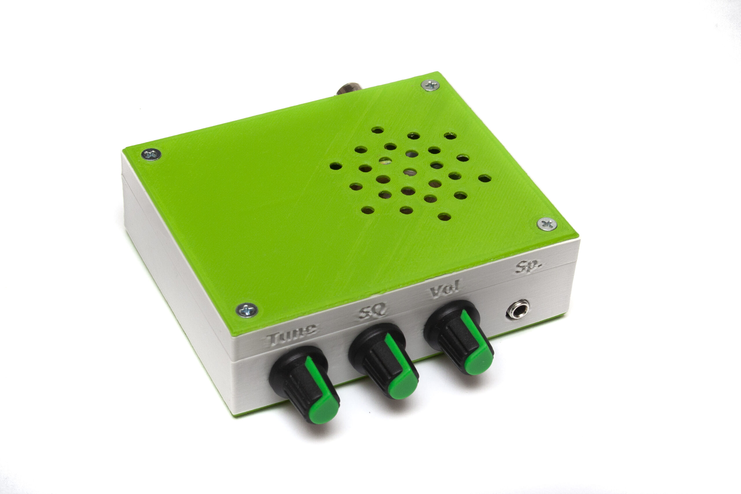
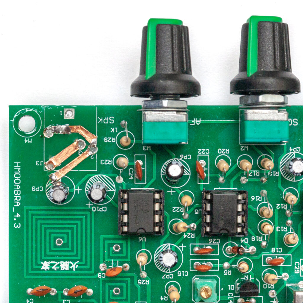
3. Speaker Output Fix
According to the original schematic, the LM386 output amplifier drives only the headphone jack. If you’d like to add a small speaker inside the case, there are no dedicated solder pads for this. You’ll need to solder the speaker wires directly to the headphone jack pins.
The headphone jack itself supports the usual auto-disconnect function: when a headphone plug is inserted, the internal switch cuts off the speaker — as in most audio devices.
However, due to the way the PCB traces are routed, this feature doesn’t actually work by default. As a result, both the speaker and headphones will play simultaneously.
To enable speaker muting, you’ll need to modify the trace layout slightly on the component side of the PCB, as shown in the photo below (not included here).

Power-Up and Tuning (“Bringing It to Life”)
The three potentiometers (left to right) have the following functions:
- TUN: tuning
- SQ: squelch
- AF: audio volume
If you’ve assembled the circuit as per the original schematic (without modifications), plug a Walkman-style headphone into the SPK (J3) jack and apply DC power to the board.
You should now hear some noise in the headphones.
If you attach a ~60 cm wire to the antenna input (J1), the noise level will increase noticeably compared to having no antenna.
Adjust the squelch (SQ / W2 potentiometer): at a certain point, the noise will suddenly cut out.
If you now touch one end of diode D2 (the detector), you should hear a 50 Hz hum — this confirms the circuit is working.
Since most inductors are PCB-etched, no tuning is needed for them.
If you bypass the input filter by connecting the wire antenna directly between R2 and C5, and short R21, the tuning range will expand — and you may start hearing local FM broadcast stations through the speaker.
Oscillator Alignment
The original manual claims no test equipment or tuning is necessary — but that’s not entirely true.
You’ll need to adjust the tuning range using the L1 adjustable inductor (with a brass tuning slug).
This can be done using:
- A VHF RF signal generator
- A frequency counter
- Or simply another VHF receiver
Remember: the local oscillator should be set to 10.7 MHz above the desired reception frequency.
When I first powered up the receiver, it worked between 135–170 MHz. I adjusted L1 to bring the range down to around 108–143 MHz, which required about two turns outward on the brass slug.
⚠️ Never use a metal screwdriver for tuning! Use a non-metallic tuning wand.
Best option: a ceramic alignment tool — though they can be pricey.
Personally, I carved one out of a 3 mm bamboo lollipop stick with a pocketknife — cheap, safe, and surprisingly effective. I like it better than ceramic (less fragile, and you’re less likely to crack ferrite cores).
Test Point for Frequency Measurement
To measure the oscillator frequency directly, probe pin 7 of U2 (NE602) — but only with a FET-input active probe.
Otherwise, the instrument (and probe leads) will detune the oscillator.
If you plan to build a digital frequency display, pin 7 is also the place to tap the signal from.
Easier Alignment After Mods
If you’ve performed the bandwidth-narrowing mods described earlier, tuning becomes easier:
- Turn W1 (TUN) fully clockwise.
- Adjust L1 until the receiver picks up 136.000 MHz.
- Then turn W1 fully counter-clockwise.
- Confirm that the receiver now tunes down to 118.000 MHz.
Final IF Transformer Tuning (T1)
Once you’re receiving actual airband transmissions (from aircraft or airport), fine-tune T1 for best clarity.
Typically, T1 needs about two full turns inward from the fully unscrewed position (counted from the top of the shield can).
Don’t Have Test Equipment? Head to the Airport!
If you don’t have a VHF AM signal generator and you’re not hearing aircraft traffic, the best solution is to grab your receiver, tools, and a tuning wand — and head to a good listening spot.
I recommend the “Cargodomb” near Budapest Airport (Ferihegy), just a stone’s throw from the HungaroControl building.
There you’ll have plenty of signal strength and active transmissions to play with.
Troubleshooting
If the receiver doesn’t work at all, start by checking the obvious things first:
- Make sure the battery or power leads are correctly connected
- Check the headphone jack and speaker wires
- Inspect whether all components are properly installed and soldered
In most cases, faulty operation is due to a soldering issue, a problem with the antenna connection, or a loose/misconnected speaker wire.
Pay special attention to the orientation of:
- ICs
- Transistors
- Diodes
- Electrolytic capacitors
Make sure all these are inserted the right way around.
Also double-check that the oscillator circuit around U2 (SA602/NE602) uses the correct values for C11 and C12 — using incorrect capacitors here can prevent oscillation.
Testing the Local Oscillator
You can check whether the local oscillator is running by using a simple VHF receiver, in case you don’t have a frequency counter.
However, be aware that the oscillator signal is quite weak — for example, my GDO (grid dip oscillator) couldn’t pick it up at all.
Don’t forget: the local oscillator must operate at a frequency that is 10.7 MHz above the frequency you want to receive.
If the Oscillator Works…
…then only a misplaced or faulty component can be preventing the rest of the receiver from working.
A common issue: Y1, the ceramic IF filter, might be installed backwards.
It should be oriented so that the label faces U2 (the mixer IC).
If installed backwards, the filter will still work — but with about 10 dB weaker signal.
Voltage Reference Table
I found a table online listing the expected DC voltages at various test points and component pins.
If you have a multimeter, you can use this to help identify faults.

Conclusion
This little kit won’t rival professional airband scanners or SDR setups — but it’s not meant to. What it offers is something more old-school, hands-on, and frankly, fun: a chance to build your own airband receiver, learn a bit of analog RF theory, and actually hear planes talking overhead — all for the price of a pizza.
It’s a great weekend project, especially for those interested in aviation, radio electronics, or just curious how the airwaves sound above their city. And let’s be honest — there’s a special kind of satisfaction in hearing real aircraft comms coming through a circuit you soldered together yourself.
So grab your soldering iron, a bamboo tuning stick!And when you’re done, head for the nearest airport hilltop. Because nothing beats the moment when you hear real aircraft chatter coming through a little radio you built yourself.