The JYE Tech DSO 068 is a do-it-yourself oscilloscope kit that’s easy to assemble. Anyone who can solder well, has some basic electronics knowledge, understands a little English, and owns a digital multimeter can confidently take on the task of building it.
The kit’s list price is $79 (around 23,000 HUF at the time of writing). It can be found in some places for about $72 (21,000 HUF), but beware—some sellers offer it for twice that price. This might seem expensive compared to other DIY kits, so let’s see what you get for your money!
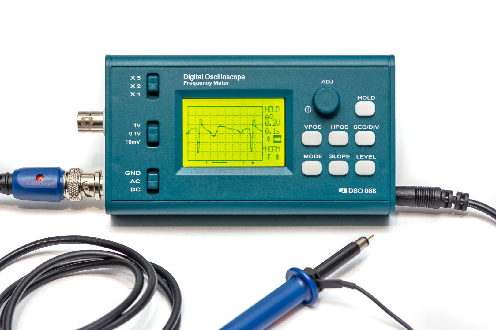
Introducing the Instrument
The DSO068 is a pocket-sized digital oscilloscope, spectrum analyzer, frequency counter, and signal generator with the following features:
Oscilloscope
- Number of channels: 1
- Analog bandwidth: 0 – 3 MHz*
- Sampling rate: up to 2 Msps
- Vertical sensitivity: 10 mV/div – 5 V/div
- Max input voltage: 50 Vpk (400 Vpk with ×10 probe)
- Resolution: 8-bit
- Input impedance: 1 MΩ
- Timebase: 0.5 μs/div – 10 min/div
- Record length: 256/512/1024 data points, adjustable
- Waveform storage: captured signals can be saved and read out via USB
* In DC coupling mode, the lower cutoff frequency is 0 Hz; in AC mode, it is around 2 Hz (–3 dB). With the maximum 2 Msps sampling rate, the Nyquist frequency is 1 MHz. In theory, it could process sine waves up to this frequency, but the waveform would be unrecognizable. While a spectrum analyzer might need only 5–10 samples per cycle, a digital oscilloscope requires at least 20–50 samples per cycle to render a readable waveform (and ideally around 200 for meaningful analysis). Thus, real-time analysis of signals above 100 kHz is not practical. Realistic measurements are possible up to about 10 kHz. Although the timebase goes down to 0.5 μs/div, sine waves can be visually identified up to around 350 kHz. Arbitrary waveforms can be interpreted reliably up to about 50 kHz.
At timebase settings of 2, 1, and 0.5 μs/div, the scope does not use real-time sampling but equivalent time sampling (ETS). In ETS mode, the image is constructed from samples taken at different moments over multiple cycles, making it usable only for periodic signals. Triggering must always be active (SINGLE mode is unavailable). Unfortunately, this feature is not very well implemented—due to trigger instability, distracting glitches appear on the screen. Here’s how a 200 kHz triangle wave looks, for example:

Additional Functions
Frequency Counter
- Measurement range: 0.001 kHz – 5000.000 kHz*
- Display: up to 7 digits (resolution: 0.001 kHz)
- Sensitivity: 0.2 Vpp
* Although rated for 5 MHz, in practice it can reliably measure a 1 Vpp sine wave up to 2.7 MHz—beyond that, sensitivity drops. When the input divider is set to the most sensitive ×1 (10 mV) mode, it reliably measures a 1 Vpp signal up to 7.8 MHz and a 0.2 Vpp signal up to 4.7 MHz.
Spectrum Analyzer (FFT)
- FFT resolution: 256 / 512 points (datasheet mentions 1024 points, but this is not selectable)
- Sampling rate: 1 sps – 2 sps
- Measurement range: 500 Hz (25 Hz/div) – 2 MHz (100 kHz/div)
- Sensitivity: 0.02 Vpp
Signal Generator
- Waveform: Square wave
- Frequency range: 1 Hz – 100 kHz, adjustable
- Amplitude: 0.3 V – 5 V, adjustable
Additional Required Parts (Not Included)
The DIY kit does not include the following components:
- Battery: KXD 383450PL M, 3.7V 650 mAh Li-Po battery (dimensions: 3.8 × 34 × 52 mm)
- JYE117 Power Switch Module
- JYE118 Automatic Li-Po Battery Charger Module
- JYE119 UART-USB Communication Module
- D5 Diode (1N4003)
In the base configuration, the unit can only be powered via USB. The USB port is used exclusively for power—the 6.5 mm barrel jack is non-functional unless additional components are installed.
If you wish to use USB for data transfer, run the oscilloscope on battery power, or supply it through the barrel jack and charge the battery, then all of these extras must be ordered separately.
Summary
All in all, this is a perfectly usable oscilloscope for low- and audio-frequency signals—for a fraction of the price of similar instruments.
Compared to something like the “Joy-it DSO138” mini oscilloscope kit (available at Conrad for 19,990 HUF), the DSO 068 has better features and a more elegant enclosure.
Here’s a video demonstration:
Assembly
Right off the bat, it’s worth noting that JYE Tech Ltd. is a Chinese company—so don’t be surprised by anything. According to the manual, the kit is supposed to include a BNC ×1/×10 oscilloscope probe (which alone is worth about 10 USD), but mine came with a basic crocodile-clip test lead instead. You could complain, but you’ll soon learn what “warranty” means when dealing with Chinese sellers…
Before you begin assembly, go through all the components to make sure everything is included and test them for defects. Since most of the surface-mount components are already soldered in place, you only need to solder resistors and capacitors, so a digital multimeter will be sufficient. If you have a component tester, feel free to play around with that too. Also inspect the PCB to verify that all parts are correctly placed. If anything is missing or faulty, order replacements (e.g. from Hestore), and only then start building.

Step 1: Mainboard Assembly
The kit comes with a brief but usable assembly guide. Thanks to the labeled component positions, it’s easy to identify where each part goes. Follow the recommended order: resistors first, then inductors, capacitors, and so on. Finally, install the optional modules. You’ll get a little plastic spacer to help position them, but you can do it just as well without. Be sure to correctly identify pin 1 of each module! First, solder a single pin, check alignment, and correct it if needed before soldering the rest. The board itself is of good quality—easy to solder and resistant to pad lift—but work quickly just in case.
The oscilloscope uses two AVR microcontrollers:
- U5 (ATmega48) handles the buttons and rotary encoder
- U4 (ATmega64) performs measurement-related tasks
You only need to solder the U4 and U5 programming headers (PGM connectors) if you plan to reprogram the AVRs later. Otherwise, do not install them. I installed them, but had to trim U4’s pins later because they interfered with the battery.
Important: Do not connect the internal Li-Po battery yet! I’ll explain more about that later.
If you want to use the 6.5 mm barrel jack for powering the device, you need to install diode D5. I initially used a MUR1100E (1A/1000V) Schottky diode, but it got hot. The 1N4003 works fine, but has a higher forward voltage drop.

The final step of assembly is attaching the LCD screen to the opposite side of the PCB. First, solder the ASSY1, ASSY2, and ASSY3 pin headers, then mount the display as shown in the guide and solder its connections.
Step 2: Power Supply Check
After completing all the soldering—except for the BNC jacks—you can begin testing. The first step is checking the power supply rails. The AVR sections won’t receive power until jumper JP4 is closed, so don’t close it just yet. The manual provides a flowchart to guide you through the power-up process and four more flowcharts for troubleshooting. Understanding which jumper to close and when is easier if you have the schematic of the power circuit:

Modules BOB4 (step-up converter) and BOB5 (negative power supply) must be installed, as they’re part of the base configuration. The battery charger module BOB2 is optional—if you skip it, bridge JP1. The BOB3 power switch module is also optional and can be bypassed with JP2. If you do install BOB3, still bridge JP2 during initial testing—BOB3 won’t function until U5 is running.
BOB3 enables software-controlled power on/off via the push-in rotary switch. Without it, you’ll need to cut power manually by unplugging the power cord. If you install a built-in battery (connected to J6), BOB3 becomes essential; otherwise, the oscilloscope would stay on until the battery dies.
If diode D5 is installed, the J2 barrel jack can supply 3–5.6 V (because of the diode’s forward voltage drop, the input must be about 0.6 V higher than the operating voltage). You can connect a wall adapter or external battery here. Regardless of D5, the device can always be powered via USB.
If BOB2 is installed (JP1 open), it will charge the internal battery connected to J6 (or external battery at J2 if JP5 is closed). This gives four possible configurations:
- No BOB2, no D5 (JP1 closed): Only USB power (default kit setup)
- No BOB2, with D5 (JP1 closed): USB and J2 barrel jack both power the unit
- With BOB2, external battery at J2 (JP1 open, JP5 closed): USB charges external battery
- With BOB2, internal battery at J6 (JP1 open, JP5 open, D5 optional): USB and J2 (if D5 installed) charge internal battery
Important: If using an internal battery, JP5 must stay open! Otherwise, power from J2 could damage the battery.
The oscilloscope draws about 250 mA during operation, and can spike over 800 mA at boot. Without a battery, make sure your power source can supply this current, or the device won’t start. A 650 mAh battery provides 2–2.5 hours of runtime (3 hours with backlight off). When USB or a 5V supply is connected to J2, BOB2 will start charging the battery.
By default, the charging current is 100 mA, set by resistor R32. The default current is fine for the suggested 650 mAh battery (slow charge ~6 hours). If you want a higher charge current, you’ll need to install R32. Use the formula:
ICHR = (R32 + 10) / (R32 · 10)
where insert R32 in kΩ to get current in amps. If R32 = ∞ (not installed) ⇒ ICHR = 100 mA = 0.15C for 650 mAh. Li-Po batteries should be charged at 0.1–0.2C for longevity; the manufacturer of the KXD 383450PL suggests 0.2–0.5C. 0.5C = 325 mA → R32 = 4.44 kΩ. Use a 4.3 kΩ (ICHR ≈ 330 mA) or 4.7 kΩ (ICHR ≈ 310 mA) resistor. Both are acceptable. Charging time drops to ~2 hours but may shorten battery lifespan.
Do not go below 1.4 kΩ—BOB2 can’t supply more than 800 mA.
Important: Double-check battery polarity! The connector on the suggested battery is wired in reverse compared to the DSO 068’s design. If you plug it in blindly, the charger module will be instantly destroyed! You can swap the wires by carefully releasing and reversing the contacts in the connector—just make sure you don’t short anything.
Always test power rails without the battery, using a bench power supply. Turn off power before soldering jumpers. If everything checks out, close JP4 to power the AVRs. When powering up again, you should see the LED blink once, then twice, indicating a successful boot. JP7 enables the buzzer—close it for sound, leave open for silence. Now that there’s load, recheck voltages. If all looks good, proceed to the next phase.
Until now, the A/D converter has been unpowered. Close JP9 to enable it. Then adjust LCD contrast and verify more voltages as described in the manual.
Step 3: Adjusting the Compensated Divider
After the power checks, connect the internal test signal output directly to the oscilloscope input. Use trimmer capacitors C5 and C8 to fine-tune a clean square wave on the screen, as shown in the manual. Repeat the process in various gain settings using SW2 and SW3.

Step 4: Final Assembly
Once everything is configured and tested, it’s time to box it up. After placing the rubber keypad and switch knobs, snap the PCB into place—it’s tricky but doable with patience. Contrary to the manual, it’s best to insert the BNC connectors after the board is secured. Mount the battery to the back cover with strong double-sided tape. Tilt the ceramic disc capacitors away so they don’t poke the Li-Po battery. Trim U4’s pins if necessary (as mentioned earlier). The specified battery fits well—don’t try anything bigger.

The charger module has a red LED connected to the LTC4054’s CHRG output. This lights up when charging (or whenever the LTC4054 enters charge mode—even without a battery). Once fully charged, the LED turns off. If the battery is too depleted to begin charging safely, the LED stays off initially. Unfortunately, the LED is located on the module, not visible from the front, but can be seen through a small gap near the rear stand.

Usage
If the power switch module is installed, the oscilloscope can be turned on by pressing the ADJ knob. To power it off, hold the knob down for about 3 seconds.
The LCD backlight can be toggled on and off by holding down the LEVEL button.
The functions of the controls and the symbols displayed on the screen are fairly self-explanatory.


Vertical Sensitivity and Position
Use the top two slide switches to adjust the vertical sensitivity. The current setting appears on the screen as “Volt/Div.”
To change the vertical position, press the [VPOS] button and then turn the [ADJ] knob.
Coupling mode (GND, AC, DC) is selected via the bottom slide switch:
- In AC mode, the DC component of the signal is blocked.
- In GND mode, the input is grounded.
- In DC mode, the signal is passed directly to the input.
Horizontal Position and Timebase
To adjust the timebase, press the [Sec/Div] button and rotate the [ADJ] knob.
To change the horizontal position, press the [HPOS] button and rotate the [ADJ] knob.
The timebase setting appears on the screen as “Sec/Div.”
Trigger Settings
To select a trigger mode, press the [MODE] button and rotate the [ADJ] knob.
To set the trigger slope, press the [SLOPE] button and rotate the [ADJ] knob.
Depending on the setting, triggering occurs on either the rising or falling edge, indicated by a symbol in the bottom-right corner of the display.
To adjust the trigger level, press the [LEVEL] button and rotate the [ADJ] knob.
A small triangle on the right side of the grid indicates the current trigger level.
The oscilloscope supports three trigger modes:
- AUTO: The trace refreshes automatically even when no trigger signal is present. This ensures the waveform is always visible, though it may “roll” across the screen if no valid trigger occurs.
- NORM: The trace is updated only when a trigger condition is met. If there is no trigger signal, the screen remains blank.
- SING: Similar to NORM mode, but the waveform is captured only once after a trigger event. Then the oscilloscope enters HOLD mode and remains there until you manually press the [HOLD] button.
If the trigger mode is set to NORM or SING, you might see no screen update. This is usually because no trigger is occurring. In such cases, it’s helpful to temporarily switch to AUTO mode to verify that the signal and trigger level are in the correct range, then return to NORM or SING as needed.
Connecting to a Computer
To use the USB functionality, you will need the BOB1 USB-UART module and a host computer that supports CP2102 USB-to-UART bridge drivers. While various drivers are available online, the manufacturer recommends downloading and installing the official version from the following link:
http://www.silabs.com/products/mcu/pages/usbtouartbridgevcpdrivers.aspx
Next, download and install Tera Term from the JYE Tech website, then launch the program. To configure the serial port, go to Setup → Serial port. The serial port configuration window will appear.
From the dropdown menu, select the correct COM port, and set the parameters as follows:
- Baud rate: 115200 bps
- Data format: 8-N-1 (8 data bits, no parity, 1 stop bit)


You can transfer both newly captured and previously stored waveform data to your computer.
To upload a newly captured waveform:
- Set the oscilloscope to RUNNING mode and perform your measurement.
- Switch to HOLD mode.
- In the menu, select SEND WAVE DATA – the device will start preparing the data for transfer.
To upload a previously saved waveform:
- Use the RECALL WAVEFORM menu to load the saved data from EEPROM.
- After loading, the DSO068 automatically enters HOLD mode.
- Select SEND WAVE DATA in the menu.

At this point, actual data transfer has not yet started—and after about 15 seconds, the DSO068 will give up trying to send.
To receive the data, Tera Term must be switched into XMODEM receive mode:
Go to File → Transfer → XMODEM → Receive.
In the dialog that appears:
- Leave Checksum selected
- Enable the Binary option

n the filename field, enter a name for the CSV file and click Save.
Transfer should complete in 1–2 seconds, and the resulting CSV file can be opened directly in Excel.

jyeLab (PC Oscilloscope Mode)
You can also download the jyeLab software from the JYE Tech website, which allows you to operate the oscilloscope from your PC.
The setup process is similar to that of Tera Term:
- You’ll need the CP2102 driver installed.
- After connecting the device via USB, you must configure the serial port within the application.
In jyeLab, use the Connect button to establish communication.
If successful, the software takes over control of the oscilloscope. The built-in display will go blank and show the message “USB Scope Mode.”
To disconnect and return to normal standalone operation:
- Click the Disconnect button in jyeLab, or
- Press the [HOLD] button on the oscilloscope itself.
