“It was still called broadcasting, and it cost a lot of money,
When the first speaker excitedly sat down at the microphone.
His ringing voice soared and flew far away,
And in one listener, something responded:
— The test was successful!”
(LGT: The Radio)
Today, digital technology is making its way into every area of communication and broadcasting. The crystal detector and Morse signals are already history. The Lakihegy cigar — though reactivated in 2006 — is now an industrial monument, and the time will come when the Solt high-power transmitter will be too. Let us recall the radio broadcasting of the early 1900s — while Kossuth Radio still spoke on medium wave!
A bit of theory
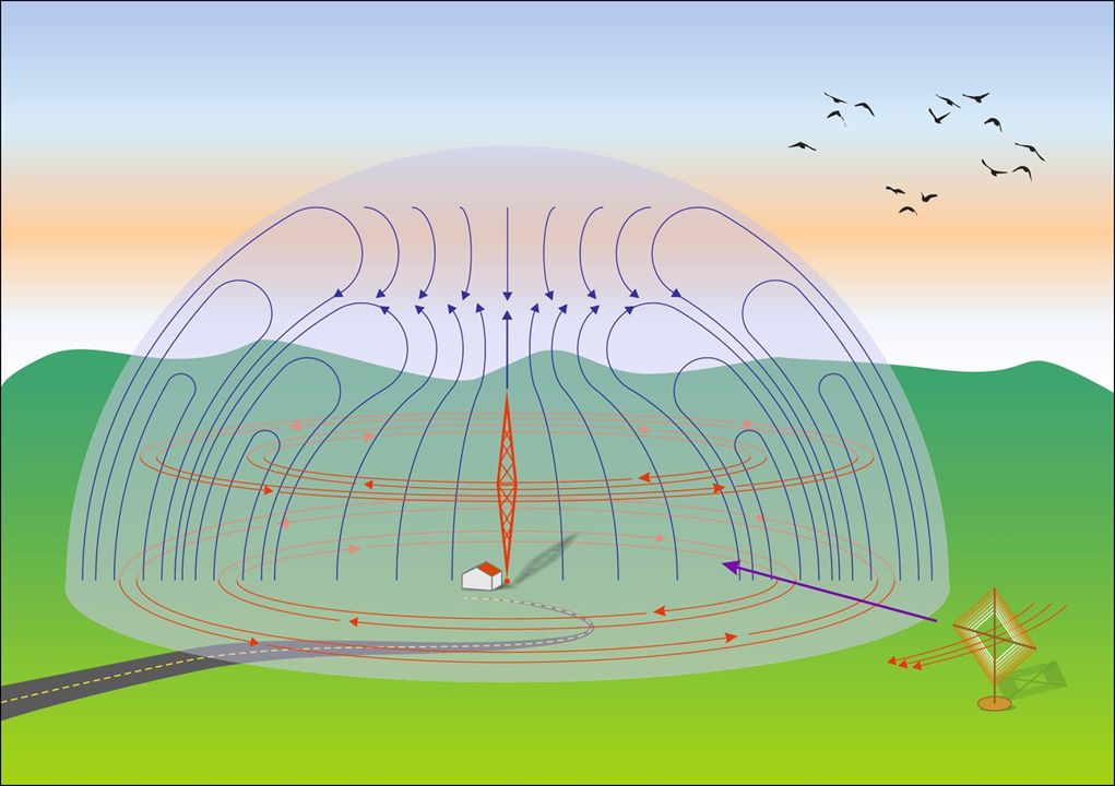
The first experimental terrestrial digital television broadcasts began in the early 1990s, but the technology only started to take off in the early 2000s. By 2015, every country will have switched over — but only in television. There are digital audio broadcasting systems (e.g. HD Radio), but the majority of commercial radio stations still broadcast analog signals in the FM band. These broadcasts can only be received in relatively small areas, because ultra-short waves travel in straight lines like light, and the receiver must be able to “see” the transmitter. Depending on antenna height and terrain, FM can only cover 80–100 km. For greater distances — without satellites — only shortwave (SW), medium wave (MW), and longwave (LW) transmissions can reach. One advantage is that AM receivers are simple in structure; 1930s radios can practically be built from components scavenged from the trash.
One issue with them is that their operation requires very high transmission power, which means expensive equipment and serious electricity bills on the transmitting end. During the war, more sensitive — and therefore more complex — AM receivers were manufactured, but FM receivers are even more complicated and expensive than factory-made AM receivers. In return, the FM provide better sound quality, and transmitter stations can be operated more economically with lower power.
AM, or amplitude modulation, is the oldest modulation technique. Its essence is that the amplitude of the radiated radio-frequency wave (the carrier) is varied in proportion to the amplitude of the audio signal (the modulating signal) to be transmitted. The simplest case is the classic telegraph mode, where the carrier is merely switched on and off in rhythm with keying — but this allows only Morse code messages. By inserting a special circuit, an AM modulator, the carrier’s amplitude can be varied, for example, with an amplified signal from a microphone, allowing speech and music to be transmitted as well.
Time is on the horizontal axis, signal amplitude on the vertical axis.
During the Cold War, long-distance medium and shortwave broadcasts served propaganda purposes against the opposing world order on both sides. In Hungary, the most well-known were Radio Free Europe (RFE) and the Voice of America (VOA), but other Hungarian-language broadcasts were also aired by the BBC, Deutschlandfunk, and from the socialist bloc, Moscow and Beijing. With the end of the Cold War, most of these broadcasts ceased, and the medium and shortwave bands have fallen silent. A few Hungarian-language broadcasts still remain, airing for about 15 to 45 minutes a day — for example, Kol Israel and Vatican Radio.
In Hungary, only MR1-Kossuth Radio still transmits in the medium wave band. The antenna, located near Solt, 83 km south of Budapest, is 303.6 meters tall — more than twice the height of Gellért Hill above the Danube. It has been operating since 1977 on the 540 kHz frequency. It provides high-quality AM reception over 80% of the country, and it can be heard throughout the entire Carpathian Basin — even in Ireland under favorable weather conditions.
The station’s systems are transistorized, but the final stage of the 2-megawatt transmitter uses steam-cooled vacuum tubes. Its power consumption — like that of similar transmission stations — rivals that of a small town. Its construction was a major state investment at the time, costing 750 million forints, which today would amount to approximately 32.5 billion forints (about €140.7 million).
Several similar high-power transmitters still operate in Europe, covering entire countries, but with our simple crystal radio receiver, only the Kossuth Radio medium wave AM broadcast can be reliably received in Hungary. Therefore, I will focus on this radio station in the rest of this article, but it can also be built to receive other radio stations.
Here’s a summary of some of the world’s best‑known medium‑wave AM transmitters, highlighting their main features — transmitter name, location, frequency, and reception range:
| Transmitter | Location | Frequency (kHz) | Power | Reception Range |
|---|---|---|---|---|
| Solt (Kossuth Rádió) | Near Solt, Hungary | 540 | 2 MW (via Nautel NX2000) | Covers 80 % of Hungary and across the Carpathian Basin; audible across Europe and parts of Asia (Medium Wave Circle, Nautel Broadcast) |
| “Shine 800” (TWR Bonaire) | Bonaire, Caribbean | 800 | ~450 kW | Targets Caribbean and South America; widely heard in the USA (Medium Wave Circle, Nautel Broadcast) |
| Moorside Edge | West Yorkshire, UK | 909 / 1089 | 400 kW (200 kW daytime on 1089) | Signals reach Scotland, Midlands, Dublin, and beyond the North Sea (Wikipedia) |
| RKS Liblice 2 | Near Prague, Czech Republic | 639 | 20 kW (reduced from 750 kW) | Now low power, lifespan extended; still in use (Wikipedia) |
| Santa Palomba (RAI) | Near Rome, Italy | 846 / 1332 | Up to 1.5 MW on 846 kHz | Nighttime reception spans much of Europe (Wikipedia) |
| Roumoules (RMC) | Southeast France | 1467 | 1 MW | Good nighttime reception within ~100 km (Wikipedia) |
| Major AM systems in Asia (e.g. NHK, China) | Various across Asia & Middle East | Various | High power (e.g. 300–500 kW) | Broad regional reach, with continued high-power use (Wikipedia) |
“And on Gyáli Street stood a closed furniture van,
And back in twenty-three, that was the very first studio.
And as for programming back then, it was good enough
If Assistant Officer János Marcal sang a song.”

Crystal Radio Receiver
Many people feel nostalgic for the beautifully polished wooden radios of the 1920s and ’30s. Those with a deeper interest in the topic should visit www.crystalradio.us, where you can find many beautifully built and interesting designs. Constructing a more advanced crystal radio receiver is not easy — despite their apparent simplicity, they require significant technical knowledge.
For rainy weekends, I recommend the retro radio building kits from Conrad Electronic for beginners and children. They come with detailed assembly instructions, from which you can learn a lot, and they can be built in just a few hours without any special tools.
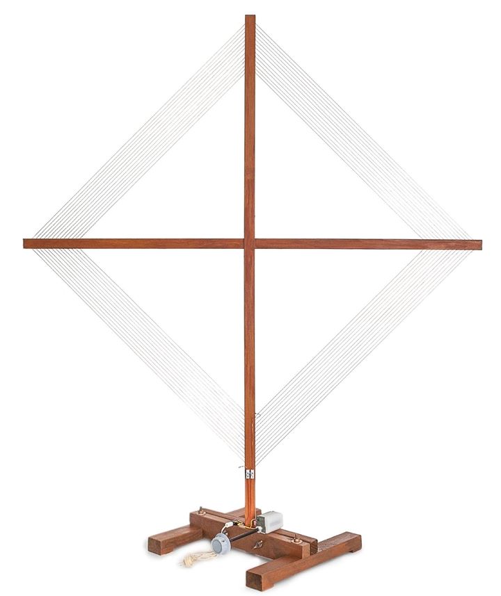
In 2014, I wrote a popular science article for IPM in which one of Nikola Tesla’s inventions, the loop antenna, served as the basis of the radio. Unlike conventional antennas, it didn’t make use of the electric component of the radio wave, but rather the magnetic field — and it also functioned as the inductance of the resonant circuit.
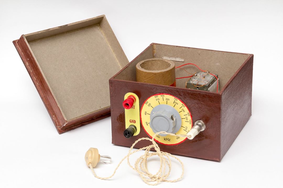
The current setup is a bit different: it’s a classic crystal radio, designed with the goal of containing no modern functional components whatsoever. In theory, that’s the case — though the connectors are contemporary, they could easily be replaced with something else. The tuning capacitor comes from an old radio, but since it’s essentially just two sets of plates, I could’ve made one out of tin cans too — just didn’t have the time.
There’s no diode, no transistor, not even a vacuum tube in the device! It requires no battery or external power source; it draws all its energy from the ether. That, of course, makes it rather quiet. As a speaker, only a so-called crystal earphone can be used — these can be ordered from eBay.
And as for the antenna: don’t even bother trying with less than about 10 meters of wire! I know the circuit could be significantly improved, but my aim this time was a minimalist design that could be assembled on a Saturday morning.
The Resonant Circuit
One of the key components of the radio is the parallel resonant circuit, which consists of a capacitor and a coil connected in parallel. The changing magnetic field induces a current in the antenna, which charges the capacitor. At the end of the charging period, the energy stored in the resulting electric field in the capacitor is released; the capacitor discharges through the antenna coil, generating a current in the wire, which in turn creates a magnetic field.
The energy oscillates back and forth between the coil and the capacitor — this is resonance. The phenomenon is similar to what happened during the collapse of the famous Tacoma Bridge: there, the wind excited the mechanical oscillations of the bridge, here, radio waves excite the electrical oscillations of the resonant circuit. The condition for resonance is the same in both cases: the frequency of the driving force must match the natural frequency of the oscillating system.
The resonant circuit can only be excited by those radio waves whose frequency (oscillations per second) matches the resonance frequency. From the cacophony of radio waves propagating around us, our device uses resonance to select the station we want to listen to. The resonance frequency depends on the inductance of the coil and the capacitance of the capacitor. If we use a variable capacitor, the receiver becomes tunable.
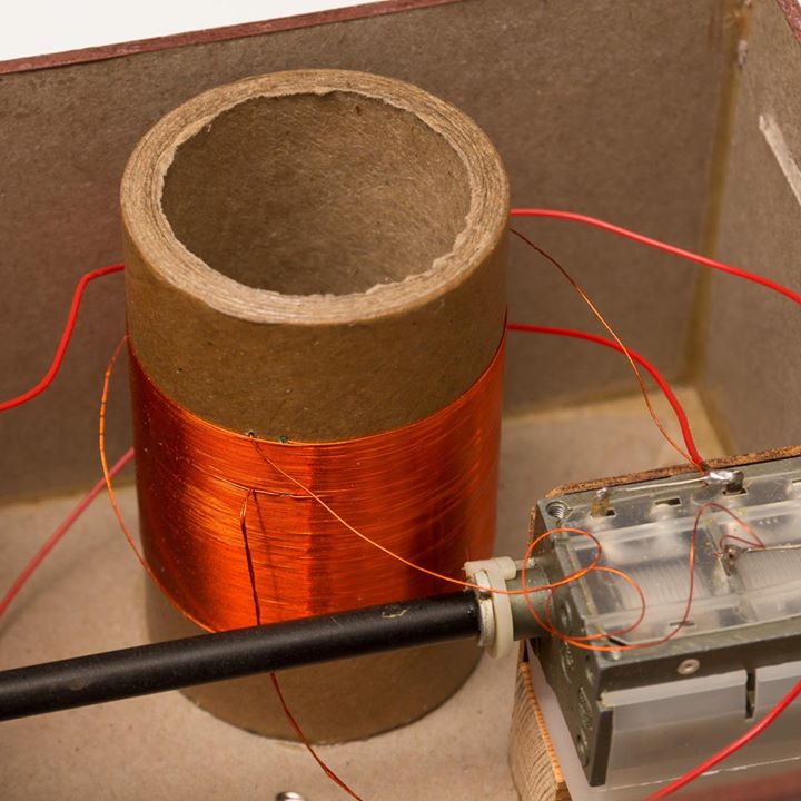
You can make a capacitor from a few metal plates and insulating foil, but out of laziness I used a factory-made 380/320 pF tuning capacitor. I connected both sections in parallel, creating a 700 pF variable capacitor, with which I designed the receiver to be tunable in the 0.4–1.3 MHz range. The best type is this kind of “air-spaced variable capacitor”, though a miniature plastic-dielectric version will also work, as long as it provides at least 650 pF. In practice, the coil’s self-capacitance turned out to be higher than expected, so the final reception range became 200 kHz to 1.1 MHz.
The coil was made on a 50 mm cardboard tube, with 120 turns, and a tap at the 30th turn, using 19 m of 0.35 mm diameter enameled copper wire. The two ends of coil L1 and the tuning capacitor C1 are connected in parallel. One end of this combined circuit goes to the antenna connector, the other to the ground terminal.
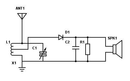
In the diagram, the upper part of coil L1 — the side connected to the antenna — has 30 turns, and the lower part has 90 turns. The tap is connected to the detector!
The Cat’s Whisker
The resonant circuit vibrates at radio frequency, tuned to Kossuth Radio at 540 kHz. What remains is to separate the carrier wave from the audio signal. In old radios, this was done using a primitive rectifier known as a crystal detector.
Various types of crystals can be used for this purpose, such as pyrite, galena, molybdenite, or germanium. The crystal is contacted by a thin phosphor-bronze needle. This wire tip gave the device its English name: cat’s-whisker detector.
The electrical resistance at the point of contact depends on the direction of current flow: it conducts well in one direction, poorly in the other. Unfortunately, not every crystal sample works well, and even different points on the same crystal’s surface can vary in quality. These types of detectors were fairly unstable and unreliable.
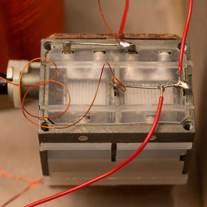
The cat’s whisker was mounted in an adjustable screw holder so it could be repositioned as needed.
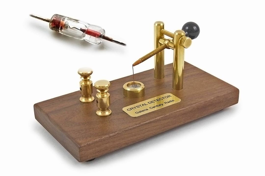
Germanium diodes like the OAA1160, OA1154, or OA1182 could be used as detectors — they can still be found here and there — but a real crystal is much more authentic! You can occasionally find beautiful vintage crystal detectors at electronics fairs, priced around 10,000–20,000 forints (approx. €43–€86). But it’s cheaper — and far more rewarding — to make one yourself!
My detector was built from a safety pin and a galena crystal — and to be honest, I’m amazed it works at all. If galena isn’t available, you can even make the crystal yourself at home (with varying degrees of success).
Mix pea-sized amounts of powdered lead and sulfur in a test tube, then heat it with a Bunsen burner. Be careful — a violent reaction will occur, producing lead sulfide. Once it solidifies, you’ll get a rather amorphous crystal which, with a bit of luck, can be used as a detector.
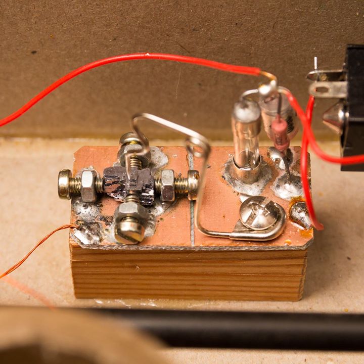
In the picture, you can clearly see a glass fuse on the right side of the detector assembly. It’s a blown fuse — I only used it as a spacer. It holds capacitor C2 and resistor R1. For C2, any film or ceramic capacitor between 1.5 and 2.2 nF will work, and R1 can be a 100–200 kΩ resistor.
If we had just suffered a nuclear strike, then — just like C1 could be made from tin cans — C2 could be made from paper and metal foil, and R1 could be created by heavily shading a piece of cardboard with pencil graphite to the right thickness. So, in theory, this radio could be built entirely from trash! Of course, where one would find a crystal earphone after a nuclear attack is another matter… but let’s not get into that.
The two ends of C2 and R1 should be connected to the headphone jack, and that’s it — we’re done! The detector continuously charges the capacitor with current coming from the resonant circuit, and the resistor slowly discharges it. The value of the resistor is chosen so that the voltage across the capacitor can’t follow the rapid oscillations of the carrier wave, but can follow the slower changes in amplitude.
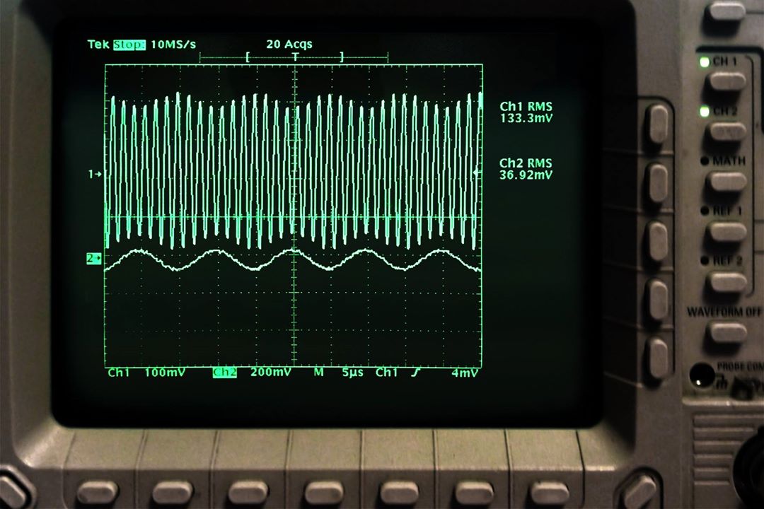
The circuit acts as a demodulator: it smooths out the AM signal, and the original modulating signal appears. If we connect a headset to the output, the sound of the radio becomes audible.
As I mentioned, this radio draws all its energy from the ether — it requires no power source to operate. That, of course, means it can only provide a very weak signal. Modern headphones are all dynamic types, with 8–32 ohm impedance, which require relatively high current — and are therefore completely unusable here!
Our radio will only work with a crystal earphone (based on the piezoelectric principle), with 2,000–4,000 ohm impedance, which consumes almost no current. These haven’t been manufactured in decades, but recently they’ve become available again on the internet — a company in Taiwan now produces them specifically for radio builders.
The 10–20 meter wire antenna can be strung between rooftops or trees. It takes up quite a bit of space, and don’t forget — it’s a lightning hazard! Back in the day, people used a spark gap lightning protector and a grounding switch for the antenna lead, and at the end of each broadcast, they would always announce:
“Don’t forget to ground your antenna!”
The device can be assembled in five to six hours. Then the antenna needs to be aimed toward Solt, the tuning knob turned, and ears opened. Our radio works well roughly within a 100–150 km radius of the Solt transmitter, covering most of the Great Hungarian Plain and the eastern half of Transdanubia. Successful reception requires patience and favorable signal propagation! On medium wave, Kossuth Radio’s programming can only be heard from 5 a.m. to 10 p.m. Reception is typically better in the early morning and worsens in the evening. In general, signal propagation is better in winter than in summer, but it also depends on weather and sunspot activity.
Public service radio programming is often criticized these days for being reminiscent of the 1950s in style. But for anyone who remembers the old slogan “form is in the content” — and vice versa — listening on a crystal radio offers perfect harmony between form and content. Here it is:
References
- Amateur Radio Textbook: http://tankonyv.ham.hu
- Dr. Endre Flórián (HA5JFV): Fundamentals of Wave Propagation – http://goo.gl/gmBf2b
- hamWiki: Logical Structure of a Radio Receiver – http://goo.gl/08d4m2
- Vintage Radio Components (old radios and modern DIY kits) – http://www.vcomp.co.uk
- Ben Tongue’s Technical Pages – http://www.bentongue.com