The other day, I explained to my partner how a fluorescent starter works and what the ballast is for. I won’t go into it now—if you’re interested, look it up. I also explained why electronic ballasts are supposedly better than traditional ones. Well, I was wrong: they aren’t better.
Every self-respecting electrician or hardware supplier website will list the advantages of electronic ballasts:
- Energy Efficiency: Electronic ballasts typically consume 20–30% less energy, which can lead to significant long-term cost savings.
- No Flickering: Electronic ballasts operate at higher frequencies (usually 20–60 kHz) compared to traditional magnetic ballasts (50–60 Hz). This eliminates visible flicker, which can tire the eyes and even cause headaches.
- Faster and Quieter Start-Up: Electronic ballasts light up the tubes instantly, without flickering and without the annoying humming sound often produced by inductive ballasts.
- Longer Lamp Lifespan: They provide a gentler start for fluorescent tubes, reducing the stress caused by high start-up voltages. This extends tube life and reduces the need for replacements and maintenance.
- More Compact Design: Electronic ballasts are smaller and lighter than traditional magnetic ones…
Well, what’s true here is that they’re lighter (5), and it’s also true that they operate at a higher frequency, so the tube doesn’t flicker (2). Point 4 is nonsense, and points 1 and 3 are very shaky.
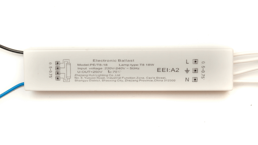
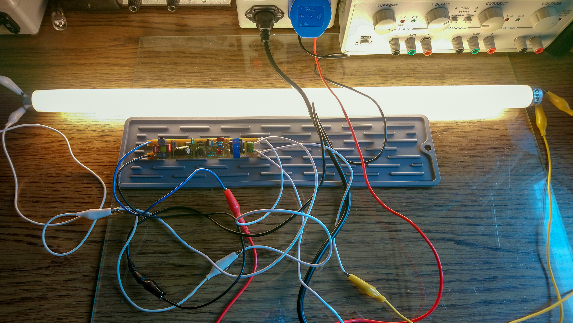
What happened was that the electronic ballast in the kitchen counter lighting failed. It was an 18W T8 fluorescent tube. A new lamp costs about €50, a new fluorescent ballast €10–12.50, and a T8 LED tube €6.50 in Hungary now. Replacing it with LED was a no-brainer—of course, the real question is how long it will last. The previous counter lighting lasted more than ten, maybe fifteen years. It used a traditional fluorescent tube and had to be replaced only because the dome yellowed over time (fluorescent tubes emit some UV). Otherwise, it was flawless. The newer one with an electronic ballast lasted about five years before the ballast burned out. The LED will be lucky to last two…
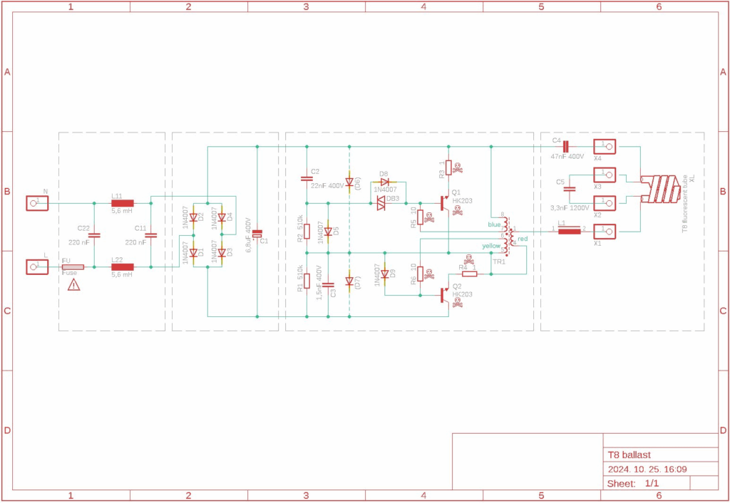
I had a little time, took the dead ballast apart, and rewired it. So there you go… eh! It’s essentially the same switch circuit that was (or is) in a lot of E14/E27 threaded CFLs. That’s also lousy, and I’ll tell you why. I’ve circled the main components with dashed lines on the wiring diagram—you don’t need to know how to read drawing symbols. From left to right:
- The first part is a mains noise filter—which, to its credit, is at least included (compact fluorescents often skip it due to space constraints). In front of it is the fuse marked FU. This should have blown, but instead the components in part 3 burned to ashes.
- The second section is a rectifier (diodes D1–D4 and buffer capacitor C1), which converts the 230 V AC into about 325 V DC.
- The third stage ignites the tube and maintains the high-frequency AC voltage. When switched on, capacitor C2 charges via R1 and R2, causing diode DB3 to pulse the base of transistor Q1, turning it on. After each activation, C2 discharges through D5, so DB3 no longer sends pulses.
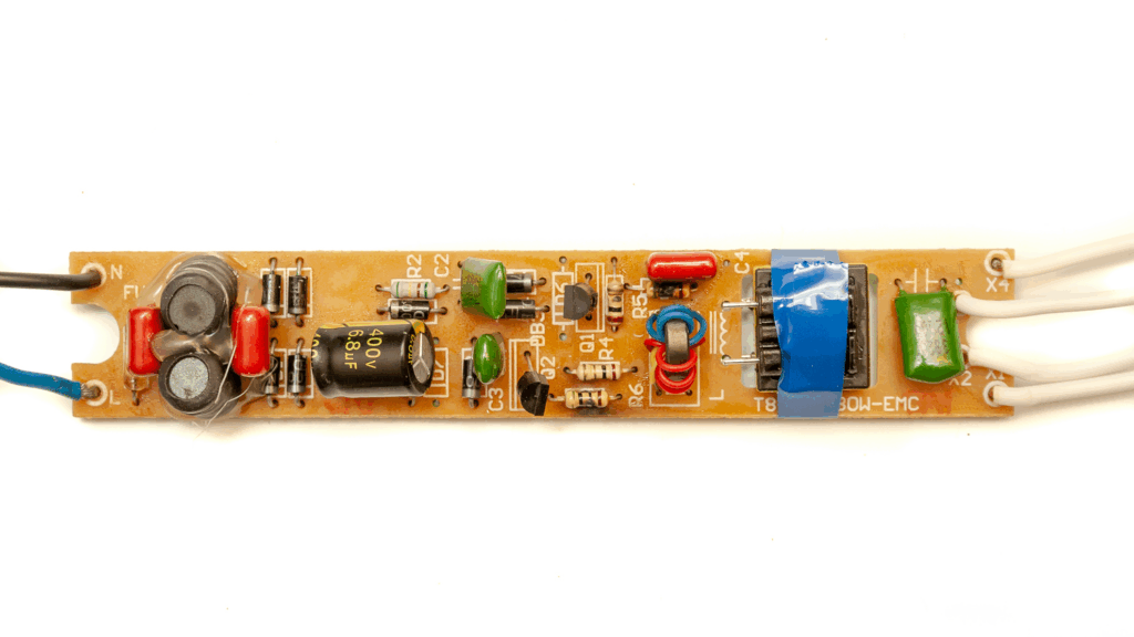
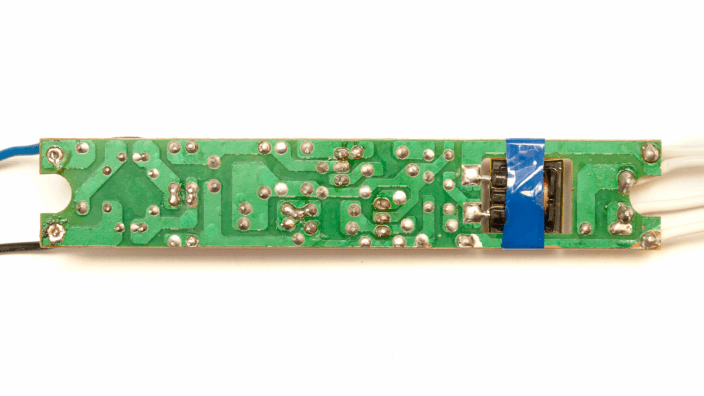
When Q1 or Q2 turns on, current flows through TR1, L1, and capacitors C4 and C5, passing through the filaments of the fluorescent lamp, which then lights up. TR1 is a very small transformer: a tiny ferrite ring at the center of the PCB, with three windings (red, blue, yellow—the latter not shown in the picture). The red winding carries the current from the tube, while the yellow and blue windings are connected to the transistor bases via R5 and R6. When one transistor turns on, current in TR1 rises until its core saturates magnetically. Then, the feedback causes the base current to drop, and the transistor turns off. At that point, the other transistor switches on, and the cycle repeats. The transistors alternate switching rapidly, around 50–60 kHz. This frequency is determined by the inductors and C5 (which, having much smaller capacitance than C4, dominates the series resonance). At this point, the voltage across the lamp and C5 is about 600 V.
The filaments at both ends of the fluorescent tube heat up, the gas inside ionizes, and a self-sustaining discharge begins in the resulting plasma. From this point, the filaments no longer need heating, as the ionization continues via collisions. Since plasma is an excellent conductor, the tube essentially shorts capacitor C5, and from then on, the resonant frequency is determined by C4. (This gas discharge stuff is 10th-grade physics, so no screaming, please! Whoever thought it was a good idea to teach this to kids was clearly out of their mind.)
Since C4 > C5, the frequency drops (I think the Thomson formula is only taught in vocational schools for electricians, not in high school physics—but correct me if I’m wrong). As the frequency drops, the voltage decreases, and the tube receives around 120–130 V, which is enough to maintain the discharge. The current is limited by coil L1 (wrapped in blue tape in the photo), just like in traditional fluorescent fixtures with magnetic ballasts.
The main issue is usually that capacitor C5—under significant stress—breaks down, which then kills the transistors too. Another problem is that if the tube doesn’t ignite quickly, Q1 and Q2 overheat and fail, along with resistors R3, R4, R5, and R6. That might be what happened in this case as well. At startup, the collector current of the transistors can spike to 3–5 times the normal operating level. The transistors in this circuit are labeled HK203 (I couldn’t find them in any datasheet), housed in TO-92 packages, and frankly look underwhelming—even many compact fluorescents use beefier ones.
If the tube is old, it’s harder to ignite, which often leads to the classic case of the aging tube taking the electronic ballast with it to the grave. In very old tubes, one of the filaments may burn out. When that happens, ignition fails, and no current flows in the TR1–L1–filament–C5–filament–C4 loop. Usually, the electronics survive this. These failures typically occur at power-on and happen so fast that the homeowner doesn’t even notice—they just see the light won’t come on.
This thing can be repaired. The burnt resistors need to be replaced (0.6W types are fine, around €0.05 apiece). The best replacement for the transistors is the MJE13003 (about €0,38 each), or possibly the 2SC2611, 2SC2482, BD127, BD128, or BD129 — though these may not last very long. The MJE13003 is more powerful and physically larger than the original, but it fits in the same place without issue. Ignoring the time spent, the total cost of the repair is under €1.25. That’s definitely something to think about. Plus, the necessary parts can often be salvaged for free from dead compact fluorescent lamps.
It’s worth noting that better-quality CFLs (e.g., some OSRAM models — though not all) sometimes include a PTC thermistor in parallel with capacitor C5 for soft-starting. This reduces the stress on the tube filaments at startup, preventing premature burnout. Of course, the downside is that the tube might last too long — users won’t replace it in time, it ages, and, as previously mentioned, ends up killing the ballast electronics. Without the PTC, the filament is more likely to burn out before the tube gets too old and weak. In other words, we protect the not-so-durable (but cheaper) electronics by sacrificing the tube prematurely. Still, the electronics aren’t meant to last forever either — which is probably why diodes D6 and D7, meant for protection, were left out, even though their positions are clearly marked on the board (they cost around €0.02 F each in retail).
This can by no means be called an environmentally conscious solution. The claimed 20–30% lower energy consumption is just greenwashing — sure, it draws a bit less power during the 1–2 seconds it takes to ignite, but during normal operation, it consumes exactly the same amount: this fluorescent tube is 18 watts, regardless of whether it’s powered by an electronic ballast or a traditional one.
The undeniable advantage of the electronic ballast is that the light doesn’t flicker at 100 Hz, which is genuinely beneficial. But let’s be honest — manufacturers aren’t doing this for our comfort. They’re doing it because it’s cheaper. Mainly because it uses less copper. A traditional ballast coil for a tube like this (18 W) contains 30–40 grams of copper, which costs about €0.20–0.30. In a typical ceiling fixture with a longer tube, the ballast can contain 100–150 grams of copper. That may not sound like much, but the total cost of a traditional ballast — with iron core, terminals, mounting bracket, etc. — is around €3.0–3.5 when made in China. An electronic ballast costs only €2.50–3.00 to produce. That’s a saving of €0.50–1 per unit. Now, consider that 1–1.5 billion fluorescent ballasts are manufactured globally every year — that kind of money is definitely worth chasing.
And let’s not forget: a traditional ballast can easily last 40–50 years, whereas the electronic ones — as we’ve seen — often fail after 4–5 years. That means ten times as many can be sold in the same market. Convenient, isn’t it?
Contrary to popular belief, fluorescent tubes aren’t that much worse than LEDs. In terms of luminous efficacy, fluorescents achieve about 70–100 lm/W; LEDs, about 110–160 lm/W. But manufacturing LED lamps actually requires more energy and materials than fluorescents. LEDs would have a smaller ecological footprint if their advertised 25,000–50,000-hour lifespans were true. But they’re not. Reliable data shows that even the best LED chips don’t last more than 15,000–16,000 hours (and fluorescents do reach 10,000–15,000 hours!).
In reality, it’s not the LED chips that fail after a few thousand hours — it’s the poorly built electronics inside the lamp. Why? Because cutting corners on the driver saves another €0.50–1, and that means you’ll end up buying five to ten times as many over the years. Imagine the situation if we had a bunch of well-made, long-lasting LED lamp factories that cost millions to build — and then the market saturated in ten years, and no one bought new LEDs. That would be a disaster… for them.
If you haven’t noticed yet, this is exactly the same as the mobile phone market: there are 8 billion people on Earth and 7.33 billion mobile phones in use, of which 6.8 billion are smartphones. Who the hell would buy 1.5 billion new phones every year (yes, that’s how many are made) if people kept using theirs for years?
Recommended readings
Understanding Electronic Ballasts
BH Estore Blog.
A clear explanation of how electronic ballasts work, their energy-saving potential, and common misconceptions.
https://bh-estore.com/blog/post/electronic-ballast-what-you-need-to-know.html
Lighting Retrofit: From T12 to T8 with Electronic Ballasts
FacilitiesNet.
Discusses the practical energy savings of switching from traditional magnetic ballasts to high-frequency electronic ones.
https://www.facilitiesnet.com/energyefficiency/article/Lamps-amp-Ballasts-Moves-from-Good-to-Better–9393
Philips LEDtube Ecofit: Product Data Sheet
Philips Lighting – Official PDF.
Technical specifications of a common LED tube, including real-world luminous efficacy and expected lifespan.
https://www.assets.lighting.philips.com/is/content/PhilipsLighting/fp929001184608-pss-global
Electric Light – Efficiency Comparison
Wikipedia.
A reliable overview of lighting technologies and their luminous efficacy, including fluorescent, halogen, and LED systems.
https://en.wikipedia.org/wiki/Electric_light
Power Efficiency of Fluorescent Fixtures with Magnetic Ballasts
Electronics StackExchange (Community Discussion).
Real-world measurements and discussion about the power loss in magnetic ballasts compared to LED retrofits.
https://electronics.stackexchange.com/questions/698714/how-much-more-energy-efficient-is-it-to-remove-the-magnetic-ballast-for-an-led-t
Fluorescent Ballasts Technical Guide
Villa Lighting Supply – Technical Document (PDF).
Detailed breakdown of ballast types, internal components, and differences in starting methods.
https://www.villalighting.com/assets/docs/PHILTGE10060_3_7-3_14_3_16_3_39_3_40.pdf