Cutting foam or polystyrene sheets with scissors or a saw is an unpleasant task, but with a hot wire, these materials are easy to slice through. You can buy hot wire cutters for just a few thousand forints, but it’s also easy to build one yourself using the transformer from an old reading lamp, a cheap coping saw frame, and a few low-cost components.
Working with foam, Styrofoam, or polystyrene sheets can be frustrating. Scissors or knives often fail to deliver clean results, leaving uneven edges and messy surfaces. On top of that, the tiny bits of material scatter everywhere and cling to everything—your hands, clothes—thanks to static electricity. A hot wire makes cutting much easier. The principle is simple: you heat a resistance wire (the cutting wire) just enough so it doesn’t glow, but gets hot enough to melt through the material.
This tool is great for model-making, decorative work, and all sorts of DIY projects. With the right temperature settings, it can even cut plexiglass or other thermoplastics, though with varying degrees of success. The result might not be as perfect as a laser-cut edge, but often, it gets the job done well enough.
Background
The PROXXON Micromot ThermoCut TC 12/E 27082 hot wire cutter for polystyrene currently retails for around 16,000 forints—without a power supply. A compatible power unit will cost you another 10,000. I wasn’t looking to spend that much, but we had an old desk lamp with a halogen bulb (rated at 35 watts) that had been retired, and it seemed like a perfect candidate to repurpose into a similar tool.
The lamp must have been haunted by the spirit of Jan Palach, as it had a tendency to set itself on fire—or more precisely, to melt the plastic housing of its own lamp head. That’s why we retired it even before LED lamps became widely available. While the casing was scorched, the internal 230V/12V, 36 VA transformer was still functional. It can supply up to 3 amps, which is plenty for powering a hot wire cutter.
What’s important is that it’s a safety transformer—meaning the primary and secondary windings are wound on separate bobbin chambers. This design ensures there is practically zero chance of mains voltage ever appearing on the secondary side, even in case of transformer failure. So it’s safe to touch the secondary terminals. Using a different type of transformer that lacks this safety isolation is extremely dangerous and absolutely not recommended for a wire cutter project.
Our halogen lamp transformer has one more advantage: it includes a built-in thermal fuse.
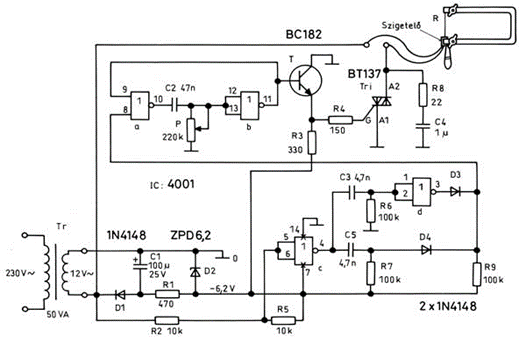
By chance, I came across a similar DIY project article in Ezermester magazine (http://ezermester.hu/cikk-1507/Muanyagvagas_konnyen__gyorsan). The circuit diagram published there is shown in Figure 1. It’s an unnecessarily complicated component graveyard—and it doesn’t even work properly. The author seems to have misunderstood how a triac operates, because contrary to what’s written in the article, a triac can be triggered by both positive and negative pulses! There’s absolutely no need for the elaborate power-supply trickery described in the text.
What’s worse, the circuit doesn’t even reliably trigger the triac. In fact, enough voltage remains on the gate to keep the triac conducting throughout the entire negative half-cycle. As a result, the control only works during the positive half-waves.
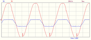
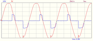
The gate voltage (in blue) and the transformer’s secondary voltage (in red) over time look like this:
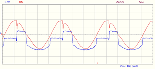
The 25V capacitor used at position C1 is inadequate—due to the spike impulses generated by the triac (clearly visible on the oscilloscope), it breaks down. Strangely enough, the circuit works with a faulty (open-circuit) electrolytic capacitor, but fails with a properly functioning one. On the other hand, if the capacitor is completely shorted, the current flowing through it will also destroy D1.
So, the circuit published in the article is fundamentally flawed—though it’s possible that due to a component failure, the person who built it believes it’s working.
The Working Foam Cutter
Due to the issues mentioned earlier, I redesigned the whole thing (see Figure 2). The result is a significantly simpler device with fewer components and more reliable triac triggering. While a triac can be fired with a pulse of either polarity, triggering is more efficient—requiring less current—when the gate receives a positive pulse during positive A2 voltage, and a negative pulse during negative A2 voltage. This is achieved with a differentiator circuit (C6–R3) inserted into the triac’s trigger path.
(This solution is also useful if you want to drive a triac using a PIC output without using an optocoupler like a MOC. In inductive loads, when triggering near the 90°/270° phase angle, the triac can generate strong high-voltage spikes at the gate. If you’re triggering it directly from a microcontroller pin through just a series resistor—the most basic setup—those spikes can easily destroy the PIC. This circuit prevents such impulses from feeding back into the microcontroller. However, it does not provide galvanic isolation, so electrical safety must be considered: the PIC section must be insulated to the same standard as the triac-switched circuitry!)
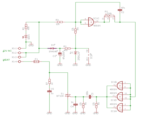
The drive pulses are generated by three gates of IC1 connected in parallel, which are fed by the IC1C–P1–C2 delay stage. This stage receives the 50 Hz signal directly from the transformer’s secondary winding. It generates pulses delayed relative to the mains zero-crossing, which are then squared up by the IC1A–D gates.
The D1–C1 rectifier provides DC voltage for IC1, regulated by R1–D2. Since the CMOS IC consumes very little current, you can use virtually any general-purpose diode for D1, and D2 can be a standard 500 mW Zener diode. Fuse F1 protects the circuit from any short circuits that may occur in the cutting wire. I used a 3.15 A fast-blow (marked F) glass fuse in a PCB-mounted holder, but if your transformer can supply more current, you can choose a higher-rated fuse accordingly. The BT138 triac is rated for up to 12 A nominally, but such high current is not needed to heat the wire.
Waveforms
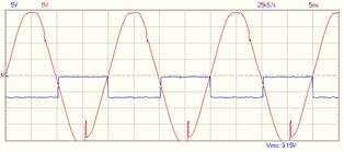
The input of IC1C (pins 8 and 9) receives a divided-down sine wave via resistors R3 and R4. This waveform is clipped by the internal input protection diodes of the CMOS gate:
At the output of the gate (pin 10), a square wave appears:
This signal charges capacitor C2 through the potentiometer. The voltage at the junction of the capacitor and potentiometer rises and falls slowly—delayed in time relative to the sine wave. The amount of delay depends on the setting of P1:
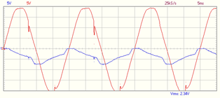
At the outputs of IC1A, B, and D (pins 3, 4, and 11), a time-delayed square wave appears:
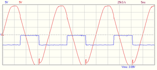
The gate of the triac receives alternating polarity pulses through the C3–R6 differentiator, which reliably trigger the triac (there is a slight asymmetry, but it’s insignificant for the operation of the device):
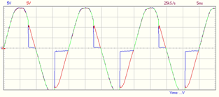
As long as the triac is not triggered, the A2 voltage (blue) follows the transformer’s secondary voltage (red), and no heating current flows. Current begins to flow near the end of each half-cycle, when the A2 voltage drops (P1 adjusts the duty cycle):
Construction
The printed circuit board layout is shown in Figure 3. The triac barely heats up, but it’s still a good idea to mount it on a small heatsink. The circuit is not sensitive to exact component values—any resistor or capacitor can be replaced with a nearby value from the E12 series (e.g., 10 k instead of 12 k). Once assembled, the circuit requires no calibration or adjustment.
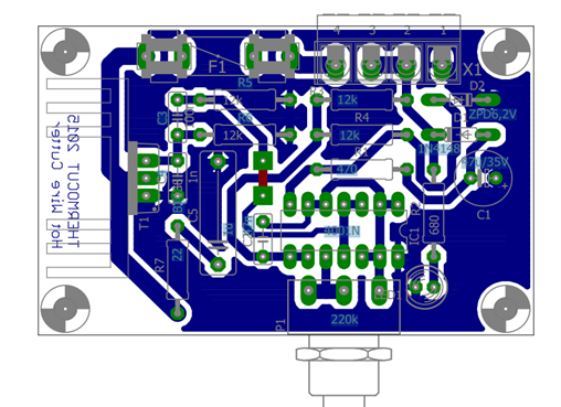
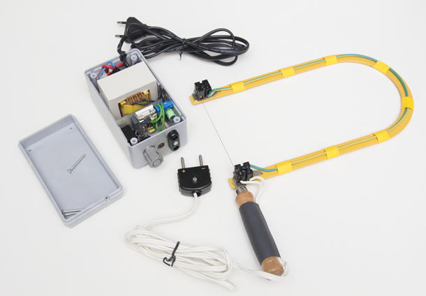
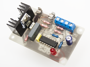
The device was housed in a shock-resistant, injection-molded polystyrene instrument case. I didn’t modify the mains-voltage part of the original halogen lamp at all—it was reused with its factory push-button switch and plug-in power cord. The transformer’s secondary winding connects to terminals X-1 and X-2 on the PCB. Terminals X-3 and X-4 are for the connector that leads to the cutting wire. This can be any two-pole connector capable of handling around 4 A of current. I used an old military-style headphone plug for this.
The simplest way to hold the cutting wire is by using a coping saw frame. Two heat-resistant bakelite terminal blocks (“chocolate blocks”) are screwed onto the frame, and the wire is clamped into these. You can find these in electrical supply stores. Make sure to use the black bakelite type—not the more common white or colored polyamide versions, as those will melt!
The wire’s hot (operating) resistance should be at least 4 ohms. A good option is a 0.3 mm heating wire salvaged from an old hair dryer, or possibly from an iron, electric stove, etc. Guitar strings can also be used, and resistance wire for heating elements is also available commercially.
A short 5–6 cm piece of resistance wire bent into a pointed shape, similar to a soldering iron tip, can be mounted on a handle and used as a woodburning tool for decorating wooden objects.
Interference Suppression
The phase-cut signal has a high harmonic content, which can interfere with radio reception or the operation of other electronic devices. The interference is strongest in the upper part of the medium wave broadcast band, and becomes negligible in the FM band. In my experience, the effect is not noticeable beyond 1–2 meters when using a typical radio receiver.
If necessary, radio interference can be eliminated by adding a suppression filter, which can be soldered onto the cutter frame’s connector afterward:
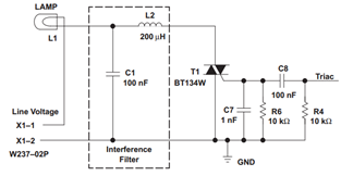
The 200 μH coil should be wound from wire thick enough to handle the current drawn by the heating wire.
Parts List
| Description | Unit Price (net, EUR) | Quantity | Line Total (net, EUR) |
|---|---|---|---|
| CD4001 Quad 2-Input NOR Gate | €0.16 | 1 | €0.16 |
| 22 Ω 5% Carbon Film Resistor, 0.25 W | €0.01 | 1 | €0.01 |
| 470 Ω 5% Carbon Film Resistor, 0.25 W | €0.01 | 1 | €0.01 |
| 680 Ω 5% Carbon Film Resistor, 0.25 W | €0.01 | 1 | €0.01 |
| 12 kΩ 5% Carbon Film Resistor, 0.25 W | €0.01 | 4 | €0.04 |
| ZPY6.2 = BZX85C6V2 Zener Diode, 6.2 V, 1.3 W | €0.05 | 1 | €0.05 |
| 1N4148 General Purpose Diode, 75 V, 100 mA | €0.01 | 1 | €0.01 |
| L-53 IT LED, 5 mm, red, transparent | €0.04 | 1 | €0.04 |
| BT138-600E Triac, 12 A / 600 V | €0.43 | 1 | €0.43 |
| PC16SH-250k Linear Potentiometer, 6 mm shaft | €0.75 | 1 | €0.75 |
| 1 µF / 100 V Film Capacitor RM15 | €0.44 | 1 | €0.44 |
| 1 nF / 100 V Film Capacitor RM5 | €0.02 | 1 | €0.02 |
| 47 nF / 100 V Film Capacitor RM5 | €0.04 | 1 | €0.04 |
| 100 nF / 63 V Film Capacitor RM5 | €0.03 | 1 | €0.03 |
| 47 µF / 50 V Electrolytic Capacitor RADIAL 6.3×11 | €0.02 | 1 | €0.02 |
| SI-CLIP B = SHH1 Fuse Holder | €0.12 | 2 | €0.12 |
| MBES152-5.08-V Terminal Block, 2-pin, RM5.08 | €0.22 | 2 | €0.22 |
| GMN-2RD Potentiometer Knob, 6 mm, red | €0.16 | 1 | €0.16 |
| 3.15 A Fast-Blow Fuse, 6.3×32 mm | €0.13 | 1 | €0.13 |
Net total (excluding VAT): €2.69
VAT: €0.73
Gross total (including VAT): €3.41
The list does not include the transformer, mains switch, enclosure, coping saw frame, bakelite terminal blocks, or wires.
The XML file required for ordering from www.hestore.hu, along with the Eagle design files, are provided in the attachment.