
Hunting meteorological radiosondes is one of the exciting pastimes of amateur radio enthusiasts.
These small instruments—launched into the stratosphere by meteorologists using hydrogen balloons—must be tracked by receiving their signals and following their trajectory based on their GPS data until they land somewhere. And those who are skillful may even take the “prey” home and give it a new life. Without a good antenna, finding the little instrument out in the field is a difficult task.
In Hungary, radiosondes are launched at 00:00 and 12:00 UTC from Pestszentlőrinc and Szeged. In addition, sondes are also launched from neighboring countries, such as Vienna, Graz, Zagreb, Belgrade, and others. Today’s sondes are single-use; the Meteorological Institute has no further need for them. If someone finds one, they may freely take it home and treat it as their own. In earlier times they had to be returned, and a small reward was paid for them.
The balloons typically rise to an altitude of 30–35,000 meters (about three times the cruising altitude of passenger aircraft). Up there it is extremely cold (–50 to –70 °C), and the air is very thin, with extremely low atmospheric pressure (0.6–0.8 kPa, which is about 0.6–0.8% of sea-level pressure). The balloon, which is only about 1.5–2 meters in diameter near the ground at launch, swells to 8–12 meters at that altitude and then bursts.
After the burst, in the thin air the sonde begins to fall at dizzying speed (around 180 km/h), then slows down as it enters denser layers of the atmosphere (to about 40–60 km/h, or around 20 km/h if it has a parachute), and finally drops to the ground or gets snagged in a tree, depending on where it falls. Since it is completely at the mercy of the winds, it can come down anywhere—forest, field, lake, river, or even the courtyard of a house or factory, or in the middle of a highway. If it happens to land in one piece—without being crushed by trucks, cows, or wild boars, and without being swept away by a river—then it can be collected.
Nowadays many people monitor these sondes, receive and decode their signals, and share the data online, for example on radiosondy.info. Based on the publicly available data, one can roughly estimate where the device has landed. However, it is not as simple as just going there and picking it up like a mushroom. Amateur stations receive the instruments’ signals from tens or even hundreds of kilometers away. This works fine as long as the balloon is several thousand—or tens of thousands—of meters high: there are data, thousands of GPS coordinates (and of course temperature, pressure, humidity, etc.).
Hunting radiosondes without any equipment
The last data typically come from an altitude of about 200–300 meters in good cases, or 800–1000 meters in worse cases, because below that the Earth’s curvature and the terrain prevent distant ground stations from receiving the radio signal. If you go to the area and look around, you may still find it with some luck.
If the device no longer transmits, then there is no option but to search, for which an 8×30 pair of binoculars can be very useful (a stronger one is unnecessary because it has too narrow a field of view). The problem is that the wind may have pushed the sonde far away from the location where its signal was last received. In undergrowth, wheat fields, or cornfields, finding the device can be nearly hopeless even if you are just a few meters from it. But don’t give up! The situation isn’t entirely hopeless; I’ve found sondes this way before, sometimes days after they fell.
Let’s pick up the signals!
A sure find can only be expected if the instrument is still operating and continues to transmit GPS data while on the ground (this is possible for about 5–8 hours after launch; after that the device shuts down automatically so as not to interfere with the next sonde).
In the field, the sonde’s signals can be received from roughly 0.5–1 km away using any average handheld radio (capable of receiving 400–406 MHz, e.g. a Baofeng) and its accompanying rubber antenna. The signals must be decoded; I will write about the details in another article. For decoding you can use dedicated hardware, or an SDR stick with appropriate software, and you will also need an antenna.
In my experience, the small whip antennas are not sensitive enough; in forests or hilly terrain, you can often receive the signals only from 200–300 meters away. In brushwood, marshy areas, or village environments cut up by fences, this can be exceedingly inconvenient. Therefore, I decided to build a sufficiently sensitive antenna that is also small and portable.
Why a Moxon Rectangle?
The Moxon Rectangle is a compact 2-element array that approaches a full-size 2-element Yagi in gain but with a far superior front-to-back ratio and a direct match for the standard 50-Ohm coaxial cable. The Moxon rectangle was invented by Les Moxon, (callsign G6XN – author of the book HF Antennas for All Locations), it is a derivative of the VK2ABQ square.
G6XN simplified the classic Yagi-Uda two-element beam by folding the ends of a dipole and reflector to create a rectangular shape. By folding the elements and shortening their effective lengths (to about 70 % of the equivalent half-wave dipole length) he achieves respectable gain (for example up to around 9.7 dBi on 28 MHz) while providing a high front-to-back ratio. Its feed-point impedance is typically close to 50 Ω, which makes matching to coaxial feed relatively straightforward—one of its attractive practical features.
The advantages of the Moxon antenna are its compact size (it requires less physical space than a comparable Yagi), its high front-to-back ratio (which helps reject unwanted signals from the rear), and its simplicity of construction (especially for portable or field use).
Because it can be built from wire or tubing and is quite mechanically forgiving, many amateur operators favour it for deployment in restricted spaces or temporary setups.
On the flip side, some disadvantages should be noted: it is a single-band design (fine for its intended band, but not inherently broadband without compromise), and the folded structure and closely spaced parasitic element constrain its bandwidth and gain compared to large multi-element Yagis. Also, while the front-to-back ratio is excellent, the absolute gain is modest compared to big arrays, so for long-distance high-gain work there are still trade-offs.
In summary: the Moxon is a superb choice when space, simplicity, rear-signal rejection and portability is the goal.
How to build the Moxon?
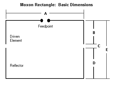
The approximate dimensions of a Moxon antenna are as follows: A ≈ 0.375 · λ; B ≈ 0.0575 · λ; D ≈ 0.0675 · λ; the total length of the folded dipole is A + 2B ≈ 0.49 · λ; the reflector is A + 2D ≈ 0.51 · λ; where λ = wavelength = c₀/f ≈ 299.79 m / f [MHz].
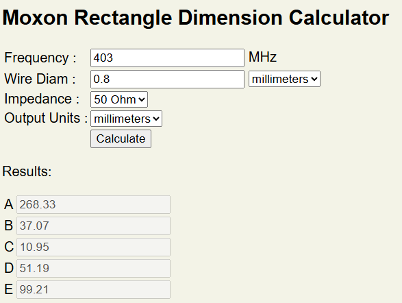
There are numerous Moxon calculators available on the internet. For practical purposes, L. B. Cebik’s (W4RNL) online calculator is perfectly adequate. It is worth looking around this site more thoroughly, as there are several useful descriptions available. It is also worth understanding how this antenna works – there are many 3D-printed Moxon-antenna designs on the internet that do not perform well because they were created without this understanding.
We size the antenna for the middle of the radiosonde band, at 403 MHz. The frame elements are planned to be made from ∅0.8 mm (#20) copper wire, and this parameter must also be specified in the program..
Antenna Simulation
We could build the antenna and test it, but we are better off doing a bit of calculation first. Let us run the computations in the free 4NEC2 simulation software. There are several tutorials for the program on qsl.net, and based on these, neither entering the geometry nor running the simulations is particularly difficult.
Bare-wire antenna
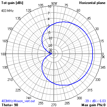
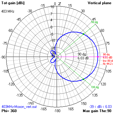
The results look very good: the antenna gain forward is approximately 6 dB, the front-to-back ratio is about 18 dB, and the impedance is around 50 Ω. Reality, however, is not this simple and not this pretty. Copper wire alone is not sufficiently rigid. To build a robust handheld antenna that performs well in the field, we can 3D-print a supporting frame and place the wire into it.
Coated-Wire Antenna
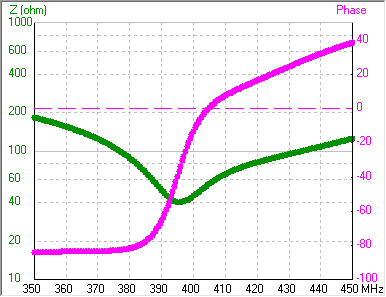
The relative permittivity of PLA (polylactic acid) is not particularly high (2.0…2.8 – the exact value can vary drastically depending on the manufacturer, additives, moisture content, frequency, and the quality of the 3D printing), yet it still has a noticeable effect: the propagation speed of the electromagnetic wave decreases due to the PLA sheath. The wave “sees” the antenna elements as longer than they actually are. Let us examine this effect for εᵣ = 2.5 and a sheath diameter of 6 mm.
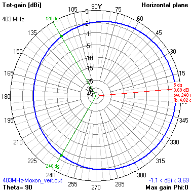
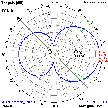
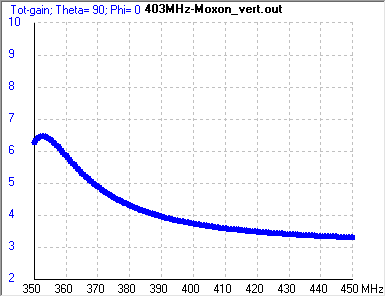
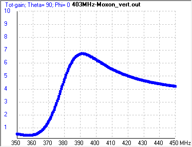
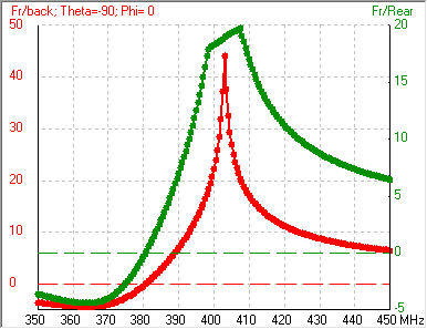
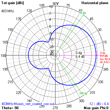
We can see that the antenna becomes completely detuned: its maximum gain shifts to approximately 353 MHz, and at 403 MHz it delivers only about 3.5 dB of gain. The radiation pattern also deteriorates, with the front-to-back ratio dropping to only about 5 dB. This issue can be resolved by shortening the antenna elements. With a 6 mm-diameter PLA sheath, the resulting shortening factor is approximately 0.85, which is quite large because the plastic layer is thick (for typical insulated wires it is only about 0.95–0.98).
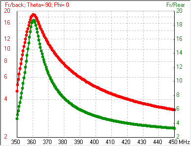
Shortened Antenna
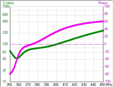
In most antenna-design programs it is possible to specify a shortening factor, which depends on the element thickness and, in the case of insulated elements, on the dielectric sheath as well. However, W4RNL’s calculator does not allow the latter. Fortunately, all dimensions of the Moxon antenna scale approximately linearly with wavelength, and all antenna elements have identical insulation, so we can simply apply proportional scaling: A ≈ 227.5 mm, B ≈ 31 mm, C ≈ 9.5 mm, and D ≈ 43.5 mm. Let us examine the properties of the modified antenna.
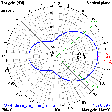
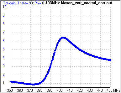
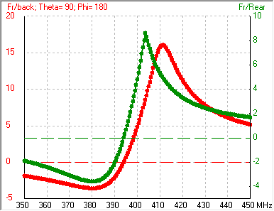
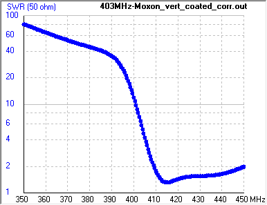
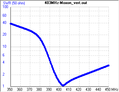
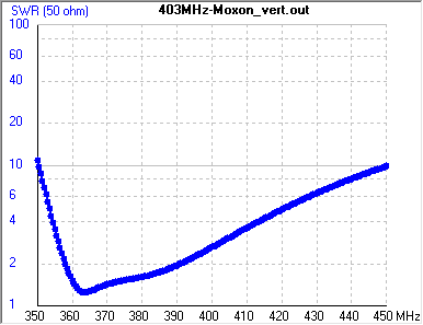
The SWR (standing wave ratio) indicates the proportion of power reflected at a given frequency – it would matter if we wanted to transmit with the antenna, but since we are only using it for reception, it is not important here. Because we are using only a short length of coaxial feeder, we will not be overly concerned with precise impedance matching either. Our goal is to achieve high gain in the desired frequency band and sufficiently good directivity for direction finding. This antenna meets these requirements.
In the calculations I assumed that the relative permittivity of the PLA print is εr = 2.5. In reality, this value may lie between εr = 2.4 and 3.0, and depends strongly not only on the raw materials but also on the print quality, infill density, temperature, etc. The procedure in which we arbitrarily change the value of a parameter and examine how this affects the results is called sensitivity analysis. Let us perform this analysis as well. For εr = 2.0 and εr = 3.0, we obtain the following characteristics:
It is apparent that if the dielectric constant decreases significantly — which we do not expect for technical reasons — the front-to-back ratio deteriorates, whereas if it increases — which is more likely — it actually improves.
Assembly the Antenna
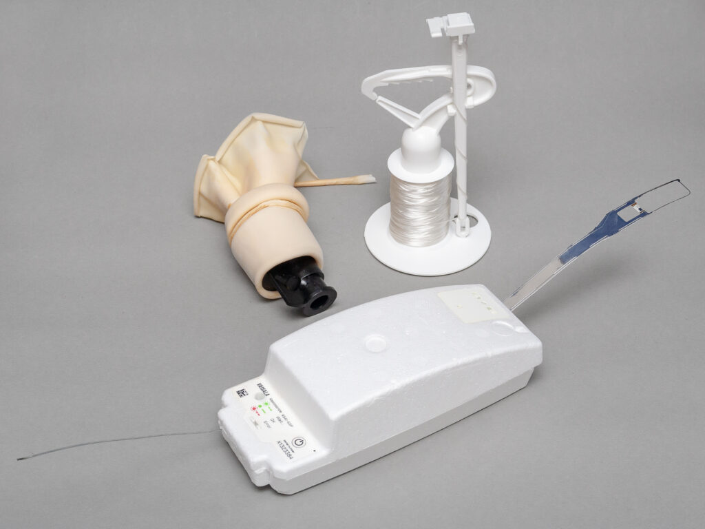
After all this, the only task remaining is to build the antenna and test it. As mentioned earlier, I made the frame from PLA plastic using 3D printing. The files required for printing are available here: https://www.printables.com/model/1489563-portable-moxon-antenna-for-weather-radiosonde-hunt.
The frame consists of two parts (so it can be printed on most printers). The two parts must be glued together. Then, attach the right-side shell to the boom (looking from the rear toward the antenna). Cut the wires to length and fit the pieces into the notches on the frame once the previous glue joints have set.

Thread the coaxial cable through, and solder its end directly to the dipole as shown in the picture. Finally, glue the left-side shell in place as well, which covers the coax.
Glue the thin cover strips in place; these secure the wires by covering them.
The boom is a rigid PVC electrical conduit with a 14 mm diameter. The handle comes from a used PU-foam applicator gun, but in case someone does not have such a handle, I am providing a 3D-printable file for it as well. The handle is fastened to the tube with an M4 screw.
I have used the antenna several times in the field, and it has proven effective for me. If you connect a small VHF/UHF radio that can receive on 400 MHz (e.g., a Baofeng), it can be used directly for direction finding. It can also be used with an RTL-SDR stick or an RDZ_TTGO radiosonde receiver, which makes accurate coordinate decoding possible in the field.