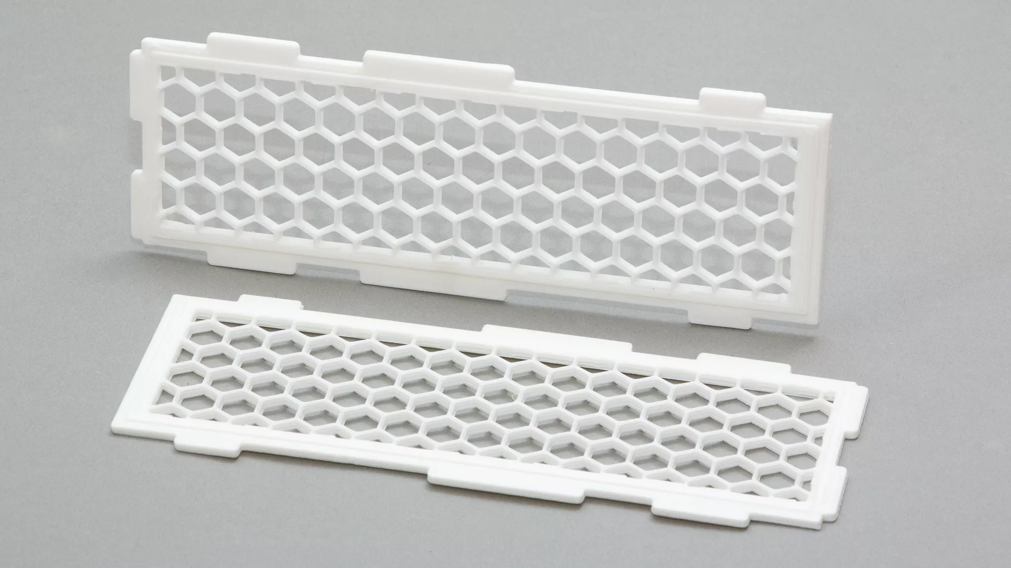
How can we make 3D-printed grilles using Autodesk Fusion 360 and PrusaSlicer? A grille looks like a simple part: a few holes, a few ribs, done. In 3D printing, however, it is precisely with objects like these that we find out how differently the design program and the slicer think.
For a flowerpot guard, a cat-proof plant cover, a ventilation insert, a speaker grille or a simple filter plate, we can choose from three basic routes. We can draw the grille as actual geometry in Fusion 360; we can create a solid body from which PrusaSlicer’s infill draws a perforated structure; or we can use a modifier body if a gridded surface is needed only on one part of the model.
The three methods are not meant for the same purpose. The right solution depends on whether we want a dimensionally accurate, installable part, or a rapidly adjustable, experimental print pattern.
1. The grille is created in the model
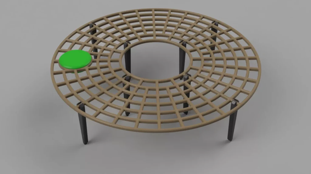
The traditional engineering route is for every rib and every opening of the grille to be part of the model. In Fusion 360, this usually consists of sketches, extrusions, cuts, and circular and rectangular patterns. For a circular flowerpot guard, the outer rim can be drawn first, then the inner opening around the plant stem, followed by the concentric rings and radial ribs. The snap-in legs, screw holes or removable segments are designed in the same model.
The main advantage of this is that what we see is really included in the STL or 3MF. The grille is not a printing trick, but an actual part. If the rib is 3 millimetres wide, then we design a 3-millimetre rib. If the hole needs to be 8 millimetres because a screw head, cable or plant stem requires it, then it will be that size. Fusion’s patterning tools are designed precisely for repeating identical elements in an ordered series: Rectangular Pattern can repeat faces, bodies, components or operations in straight directions, while Circular Pattern can repeat them around an axis.
When printing, however, that level of detail comes at a high price. The slicer treats every small rib of the grille drawn in CAD as a wall. The nozzle traces around the small cells, creates perimeters, makes short internal infills, repeatedly accelerates, slows down, and jumps from one island to another. This can make the part dimensionally stable and strong, but it also increases printing time, G-code size, the number of seams and the chance of errors. Material buildup, small bumps, stringing or signs of overextrusion can appear especially at grille junctions.
A grille modelled in Fusion is the best choice when the grille is a relatively coarse, functional part: it snaps in, is screwed on, carries loads, fits precisely, or the size and position of the holes matter. For a ventilation grille, for example, the frame, mounting hole, spacer and snap-in tab should be CAD geometry.
Advantages
- Accurate, scalable geometry: the ribs, holes, rims, tabs and fasteners are real model parts.
- A well-documented design that can be reopened: the dimensions can be modified in Fusion’s parameters.
- Stronger, more controlled frames: the slicer creates perimeters around the ribs, which in many cases produces a stiffer part.
- Ideal for installable parts: screw holes, snap-in tabs, hinges, spacers and fits can be designed precisely.
Disadvantages when printing
- Many small perimeters and many short print paths are created, which increases printing time.
- Because of the many small openings, there may be more seams, retractions, stringing and bumps at junctions.
- With ribs that are too thin, the slicer may omit details or simplify them into a single, fragile toolpath.
- For large, repeated grilles, both the CAD model and the STL can become cumbersome; slicing may slow down.
- Changing the grille geometry is slower: the pattern is determined not by a slicer setting, but by the structure of the model.
2. The grille is drawn by the infill
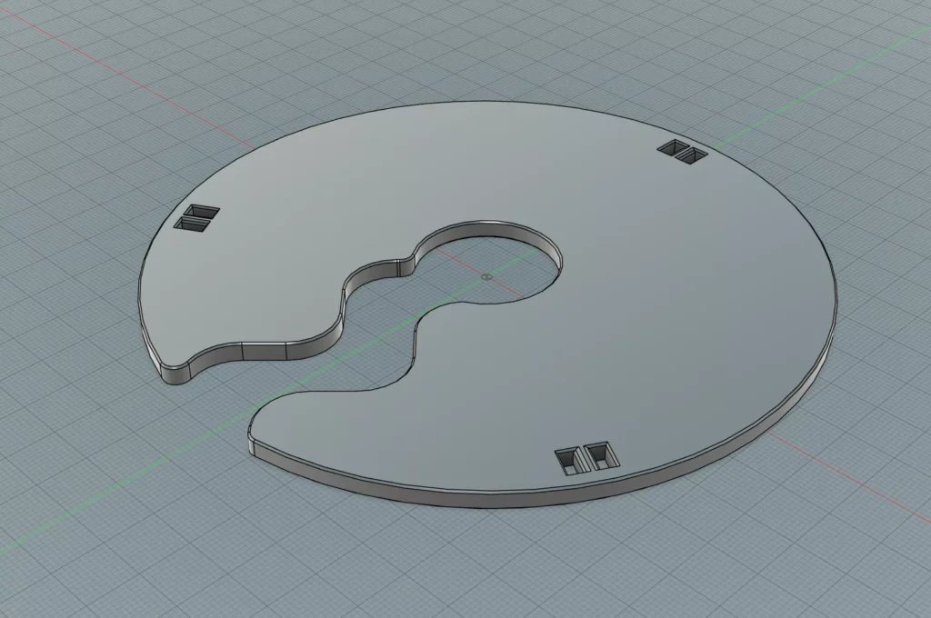
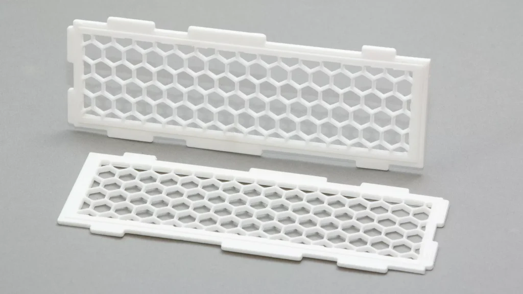
At first, the second method seems like cheating, but from a practical point of view it is distinctly elegant. In CAD, we do not model a grille; instead, we model a solid, flat body. This is the simplified version of the flowerpot guard shown in the picture: a disk-like or horseshoe-shaped plate, with a cutout in the middle but without grille openings. The grille is not made in Fusion; it is made in PrusaSlicer by making the infill pattern visible.
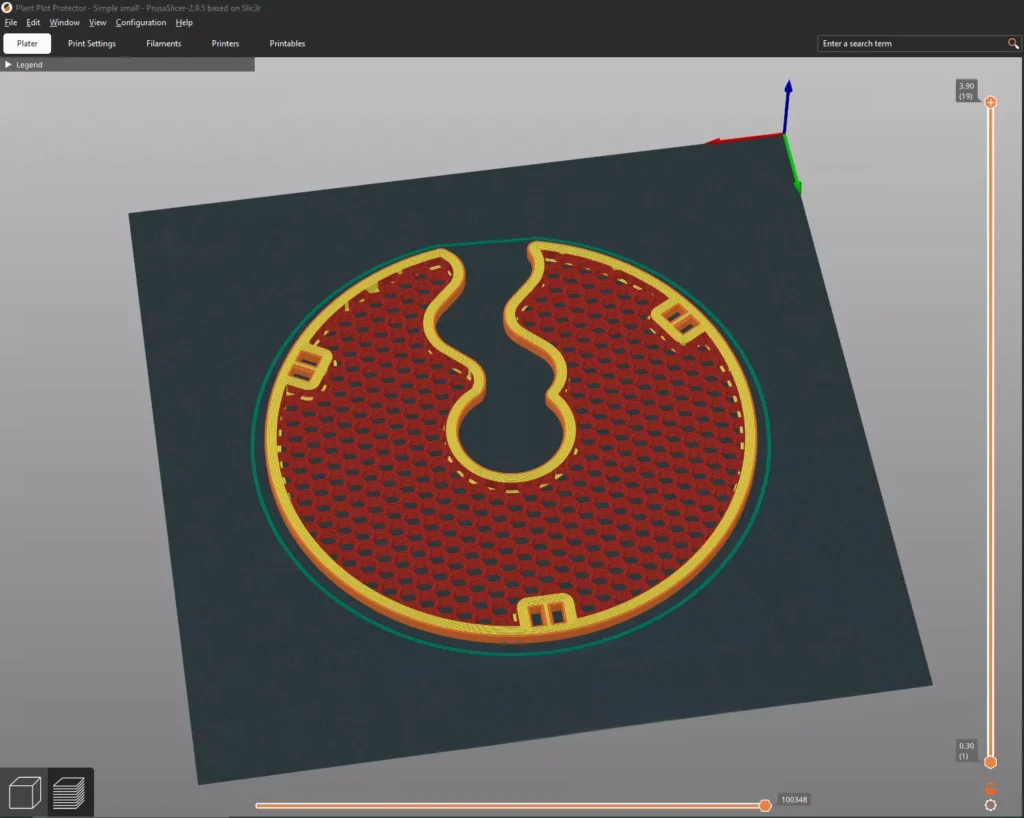
The logic is simple. Normally, the slicer fills the inside of the object with infill, then closes it off at the top and bottom with solid layers. If we set the number of top and bottom solid layers to 0 (which in PrusaSlicer really turns off the closing layers), the internal infill becomes visible. The infill pattern itself then becomes the grille. The infill pattern and density can be selected in a separate menu item.
For flat filters, decorative inserts and quickly replaceable ventilation grilles, this is the fastest working method. In Fusion, only the part outline, thickness and mounting points have to be drawn. The grille pattern can be changed in PrusaSlicer with a single setting: honeycomb, grid, triangles, rectilinear, gyroid or another infill. The hole size is not specified directly in millimetres; instead, it is determined together by the infill density, the extrusion width and the pattern.
Basic setup in PrusaSlicer
- Import the solid, flat model.
- Print Settings -> Layers and perimeters: Top solid layers = 0, Bottom solid layers = 0.
- Print Settings -> Infill: choose a Fill pattern value.
- Fill density: 30-50% is a good starting range; a lower value gives larger holes, while a higher value gives a denser grille.
- Print Settings -> Advanced: if the ribs look too thin, the infill extrusion width can be increased.
- Print Settings -> Layers and perimeters: set the perimeters to be thicker than usual if we want the grille to have a solid frame.
- After slicing, always check in Preview view whether the desired grille has really been created.
The choice of pattern is not merely an aesthetic question. Honeycomb is visually striking and provides good general stiffness; grid creates the effect of a classic ventilation grille, but more material may accumulate at the intersections; triangles is stiff and has a more technical appearance, especially in a flat part. Rectilinear is fast and material-saving, but gives less of a “grille plate” impression. Gyroid is visually striking and can provide more continuous print motion, but as a decorative vent it is not always as immediately legible as a square grid or honeycomb.
The great advantage of this method is that the grille is part of the slicing profile. From the same solid model, a dense cat guard, a more open vent or a decorative insert can be made with a few clicks. The disadvantage is the same: there is no grille in the STL. If we send the file to someone, they receive only the solid plate, and with different settings they will print something different. The grille is preserved together with the PrusaSlicer settings, most reliably in the 3MF project file.
There is one more important difference. In an infill-based grille, no separate perimeter is created around each individual grille opening. This often gives a cleaner and faster print, because there is less short tracing around and fewer seams. In return, the edge and placement of the grille openings are less “engineering-grade” precise, and the grille depends on the slicer’s internal algorithm, the printer and the nozzle diameter.
3. Modifier body: grille only where needed
The third route is useful when the goal is for most of the object to remain solid, but for a certain surface to provide ventilation. A typical example is the side wall of an electronics enclosure: the housing should be closed and strong, but a gridded area is needed above the power supply or the controller board. In such cases, it is not necessarily worth cutting the openings in Fusion. PrusaSlicer’s modifier bodies are intended for applying different slicing settings to a selected spatial part of the model.
The principle is this: the modifier body is not a conventional part, but a settings mask. Where it intersects the model, the infill, perimeter count, number of top and bottom layers, extrusion width or other printing parameter can be different. This makes it possible to designate a rectangular zone on the side of the box where the top and bottom closing layers are 0 and the infill is, for example, honeycomb or grid.
Steps
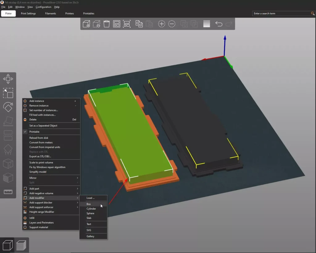
- In the 3D view, right-click the model.
- Choose Add modifier -> Box, or another suitable shape.
- Scale and move the modifier body to where we want the gridded zone.
- In the object list on the right, click the Generic-Box element, then Add settings -> Layers and perimeters.
- Enable the Top and Bottom layer settings, then set them to 0.
- If necessary, also add the Infill density and Fill pattern settings so the grille zone receives a different pattern or density from the rest of the object.
- After slicing, check layer by layer in Preview view that the grille appears exactly where we planned it.
This method is especially useful for prototypes. On several sides of an electronics enclosure, we can try out where the ventilation should be without having to redraw the CAD model each time. At the same time, it should not be forgotten that the modifier body changes a slicing setting; it does not create a real geometric cutout. If the opening has to fit a fan, screw or filter insert with dimensional accuracy, the frame and the fasteners are still better designed in Fusion.
For a grille made with a modifier, the question of perimeters is especially important. If the slicer tries to surround every small hole with independent walls, the result may be too dense, slow or unattractively seam-covered. If, however, we reduce the perimeter count in the grille zone to 1, or in some cases to 0, we can get a cleaner, more infill-like pattern. This should not be set blindly: the Preview view is decisive. If unexpected walls, closures or material buildup appear at the boundary of the modifier, it is better to change the size of the zone, the perimeter count or the CAD geometry itself.