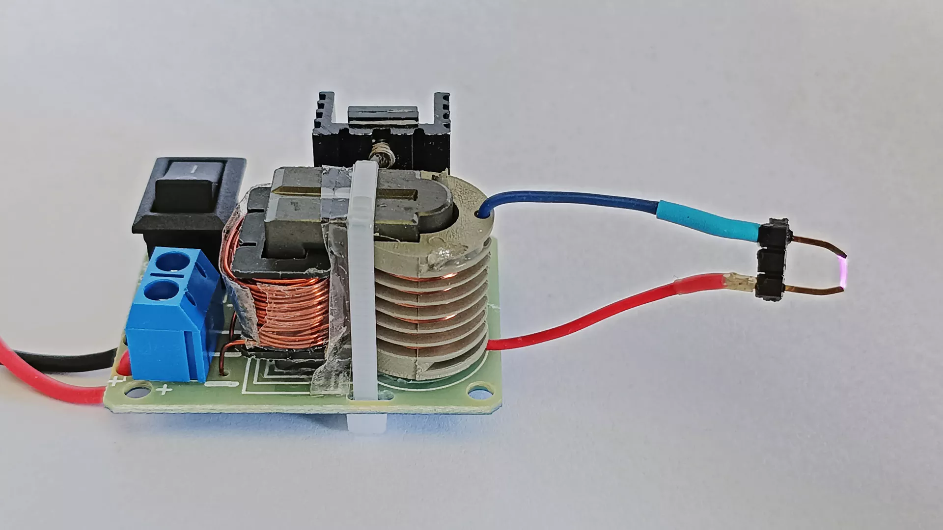
The module shown in the picture can be purchased online for around 2–3 euros. It is a small “15 kV” generator suitable, for example, for secondary-school science experiments or for use as a negative ion generator/air ionizer. The circuit can produce a stable, high-temperature, high-frequency arc, which can easily ignite small combustible materials, such as a sheet of paper.
This is undoubtedly one of the most basic and most easily accessible kits for beginner electronics enthusiasts who want to explore the world of high-voltage applications. Assembling the module requires minimal knowledge, and no circuit-level adjustments are needed.
Although its power is not high, even a minor accident can cause fire or electrical burns. The device is capable of producing impressive small high-frequency arcs, which can be admired if the proper safety precautions are observed.
Input current: ≤ 2 A
Output voltage: approx. 15 kV max.* — use with due attention to safety
Output current: ≤ 0.4 A
High-voltage ignition distance: ≤ 0.5 cm
* Note: 15 kV according to the manufacturer; in reality, it is closer to 12 kV—above 15 kV, the transformer winding punctures (breaks down) and can be destroyed.
If you want to estimate the voltage based on an existing spark, a rough rule of thumb is to calculate with 3 kV per millimeter (or 1–1.5 kV in the case of pointed electrodes).
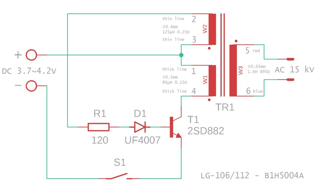
Components
1 × 15VKE step-up transformer
1 × 120-ohm resistor
1 × UF4007 ultrafast diode
1 × 2SD882 (D882) transistor — NPN, 3 A, 40 V, 10 W, TO-126/SOT-32
1 × heatsink for the transistor
1 × M3×6 screw
1 × rocker switch (KCD11-2P)
1 × pin header
1 × PCB, size: 42 × 32 × 1.6 mm
1 × cable tie
Recommended but not included in the kit: 1 × KFS-5.0-2P screw terminal block for the power leads; the PCB is designed for this connector.
Transformer construction: high-frequency U-shaped ferrite core, approx. 27 × 16 × 21 mm. It has two primary windings: a drive winding and a feedback winding. The secondary winding is designed for a maximum output of 15 kV; the limit voltage must not exceed 15 kV. The arc length is one centimetre; a higher output voltage may damage the transformer.
Assembly
Solder the components into the PCB starting with the lowest-profile parts and working toward the tallest ones: begin with the resistor and the diode, then the switch, followed by the transistor, and finally the transformer. The terminal block, if used, should only be installed after the transformer, because it makes access to the transformer wires difficult.
The transformer can be secured to the PCB with the supplied cable tie, following the pattern printed on the board. The cable tie should be threaded through the elongated holes. For a neat result, the locking end should be above one of the holes, on the underside of the PCB. The transformer will still slide around even if the cable tie is tightened, so it is worth putting a drop of adhesive between the core and the PCB beforehand, for example rubber cement, which does not set permanently.
The transformer’s primary windings have four leads: two thick CuZ wires, 0.5 mm in diameter, and two thin CuZ wires, 0.4 mm in diameter. The PCB has three soldering points: a central one with two holes, and two outer ones. One thick wire and one thin wire must be soldered into the central pad in such a way that the left-hand lead of the thick wire and the right-hand lead of the thin wire are connected there — or vice versa: the right-hand lead of the thick wire and the left-hand lead of the thin wire.
The other lead of the thick wire must be soldered into the solder pad at the edge of the board; this connects to the collector of the transistor. The other lead of the thin wire must be connected to the outer solder pad closer to the centre of the board; this connects to resistor R1.
Care must be taken when soldering. The quality of the PCB is “moderate”; if it is overheated, the solder pads can easily lift off. The transformer leads, the CuZ wires, cannot be soldered as they are. The enamel insulation must first be removed. Carefully — so as not to break the wire — scrape it clean down to bare metal all around, on every side, using fine sandpaper, a scraper knife, or a blade, then tin it beforehand.
Chemical enamel removers also exist, but we probably do not have any of those — and in any case they are dangerous caustic substances. An old trick is to press the wire onto an aspirin or Kalmopyrin tablet with the hot tip of the soldering iron. The acidic fumes released will strip off the enamel, but they will also damage the soldering-iron tip, so this should only be done with a worn-out or expendable tip. Another method is to hold the end of the wire briefly in the flame of a lighter until the enamel blackens and burns off. The soot can then be wiped away with a cloth or fine paper.
Certain types of enamel — so-called solderable enamelled wires — melt off by themselves at higher temperatures, around 350–400 °C. These can be soldered directly, without first cleaning off the enamel, but the wires used here are not of that type.
The transformer’s secondary winding, wound on a sectional bobbin, is made of very thin wire, 0.05 mm in diameter, which breaks very easily. The manufacturer has soldered a red and a blue stranded copper lead to it, and attempted to secure them by melting the edge of the bobbin over the soldered end with a soldering iron. It is quite ugly, and not particularly reliable either: the leads can move, and the winding may break. For this reason, secure the ends to the bobbin with a drop of curing plastic adhesive on each side.
If the two output wires are too far apart, the transformer will operate with no load; it may arc internally and burn out. To avoid this, solder a spark gap to the output wires, which can be made from the pin header. Break off a section of three pins, then pull out the middle pin with small pliers. This leaves two pins spaced about 5 mm apart; solder the output wires to these pins.
Operation
The input supply voltage is DC 3.7–4.2 V. Pay attention to polarity. The transformer is said to be suitable for a 12 V supply voltage as well, but for a higher supply voltage the transistor’s base resistor must be increased to 150 Ω … 1.5 kΩ. The resistance must not be too low, otherwise the transistor may burn out, but it must not be too high either, otherwise the circuit will not start oscillating.
The output voltage must not exceed 15 kV, otherwise the transformer may be damaged. A spark longer than 0.5 cm must not be produced, because the transformer may arc internally and burn out. The device is designed for short operating periods. If the user wishes to use it for continuous operation, it is recommended to pot the winding with insulating wax or epoxy resin.
The circuit is a simple so-called blocking oscillator. When switched on, the transistor receives a small base current through the feedback winding and turns on. Collector current begins to flow through the drive winding. The flux in the core increases, and a voltage is generated in the feedback winding, which drives the transistor further on. The current continues to increase until the flux can no longer build up, either because the core saturates or because the current reaches the maximum value allowed by:
supply voltage – transistor VCE / winding resistance
At this point there is no further change in flux, no additional voltage is generated in the feedback winding, and the transistor begins to turn off. The decrease in collector current causes a decrease in flux, which again generates a voltage in the feedback winding — but this time with the opposite polarity, tending to turn the transistor off against the base current. The process continues until the flux falls to zero. The cycle then starts again.
The function of the diode is to block the reverse voltage pulse generated by the collapsing magnetic field of the transformer, which could otherwise destroy the transistor.